
DESCRIPTION Safety coupling with linear limitation of force. Releasing both compressive and tension once it reaches the calibration force. The setting force can be adjusted by turning the adjuster nut onto the springs and re-engagement is automatic. The possibility of connecting linear motion is also very distant from each other. No axial play Protection in […]
Torque Limiters
Regal Rexnord Introduces Redesigned Autogard® F400 Series Torque Limiter
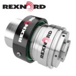
Regal Rexnord Corporation has launched a redesigned series of its long-serving, Autogard F400 Series torque limiter. This next-generation Autogard F400 Series offers significant improvements whilst remaining a drop-in replacement for the legacy 400 Series, matching its predecessor in form, fit, and function. Autogard torque limiters act as a mechanical circuit breaker to protect a drivetrain, […]
Voith torque limiting coupling with controlled slip
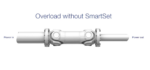
SmartSet is a torque-limiting coupling with controlled slip based on the same technology as SafeSet, with the additional ability to also slip without releasing, to reduce the short duration and dynamic torque peaks without interrupting production. The SmartSet principle is simple: controlled slip torque for process improvement. The SmartSet coupling can safely slip up to […]
Voith torque limiting couplings
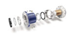
Protect your driveline with intelligence Drivelines in rotating equipment are long-term investments, worth protecting. Every minute of unplanned downtime caused by overload, is a loss in production. With outstanding safety and reliability, Voith’s torque-limiting couplings protect all components in the driveline, resulting in smooth operation, less wear and tear, and maximum performance of your equipment. […]
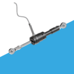
ComInTec axial force limiter
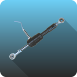
Safety coupling with linear limitation of force. Releasing both compressive and tension once it reaches the calibration force. The setting force can be adjusted by turning the adjuster nut onto the springs and re-engagement is automatic. Possibility of connecting linear motion is also very distant from each other. No axial play. Protection in both tension […]
ComInTec rollers torque limiters
Safety coupling with the transmission of motion through rollers that allow complete disengagement when the calibrated torque is reached, permitting a quick stop of the transmission due to micro-EM1. Suitable for transmitting high torque with high reliability and compact size. * Precise torque setting by adjusting the radially balanced locking nut. * The innovative regulation […]
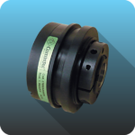
KTR RUFLEX torque limiter with BoWex gear coupling
Torque limiter with torsionally stiff curved-tooth gear coupling The torque limiter RUFLEX with BoWex gear coupling combines a torque limiter with a curved-tooth gear coupling for shaft-to-shaft connections. BoWex curved-tooth gear couplings are flexible and torsionally stiff shaft connections for a positive-locking torque transmission and are particularly suitable to offset axial, radial, and angular shaft […]
Zero-Max overload safety devices for corrosive and washdown applications
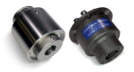
Zero-Max Overload Safety Devices protect motor and drive systems from overload while offering options to withstand corrosive environments and necessary washdowns. These options provide protection from direct water spray, washdown chemicals, detergents, chemical exposure, and debris. These unique Overload Safety Devices are ideal for applications ranging from food processing, packaging, commercial dishwashers, industrial parts washers, […]
Ringfeder on safety, reliability, and cost benefits in steel mill applications

By Ringfeder Editor In a previous blog post, we explored the role our Shrink Discs, Locking Assemblies, and Gear Couplings play in steel mill bridle roll systems, offering ease of installation, removal, and replacement. Now, let’s turn to other applications within steel mills that can benefit from our heavy-duty power transmission components. Safety Couplings Minimize […]
Magnetic couplings from Miki Pulley “Mechanically Isolate” shafts and motor
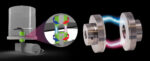
Magnetic couplings from Miki Pulley are ideal for machine designs involving food, pharmaceutical, and laboratory applications requiring a clean, non-contact connection between motor and shafts. The mechanically isolated magnetic coupling transmits torque through the air. This occurs through both input and output hubs of the coupling which contain powerful rare-earth neodymium magnets. These magnets create […]