
When looking at gearbox accuracy, there are a number of key parameters to consider. Knowing these parameters and understanding what impact they have on accuracy is critical to designing a system that meets specifications and achieves optimal performance. Below is a detailed look at each of these key parameters.
Torsional Stiffness
What is it? The torsional stiffness is defined as the quotient of the externally applied torque and the resulting twisting angle or “wind up” at the output of the gearbox. The value for torsional stiffness is typically given by the manufacturer. It is measured as torque per angle (Nm/ arcmin). For couplings, it may be referred to as torsional resistance.
How is it determined? To determine the torsional stiffness, the gearbox is loaded with a continuously increasing torque up to the nominal torque capacity while the input shaft is locked. This is repeated in the opposite direction. The applied torque and angle of deflection at the output flange are measured (see the hysteresis curve, figure 1).
FIGURE 1: GEARBOX HYSTERESIS CURVE FOR ±100% NOMINAL TORQUE
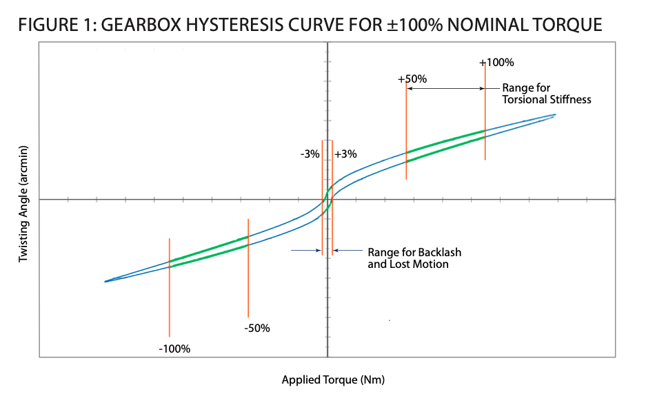
Torsional stiffness is taken from the slope of the hysteresis curve at 50% to 100% of the nominal torque. Because the curve is relatively flat in this range, the torsional stiffness is close to constant. In addition, many applications have an applied torque that falls in this range.
Similarly, you can look at torsional stiffness in other components. In couplings, it is often referred to as “torsional resistance.”

How can I use it?
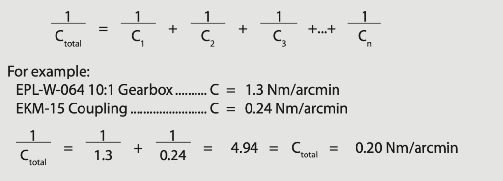
Torsional stiffness for a system is calculated using the sum of the inverse of torsional stiffness for each component. Total torsional stiffness will be less than any of the individual components.
Backlash
What is it? Torsional backlash is the error of the output shaft position in relation to the input shaft at zero torque. In a gearbox it is primarily clearance between the mating gear teeth.
How is determined? The measurement of backlash is done by rotating the output of a gearbox in both directions with the input shaft locked. The torsional backlash can also be observed in the hysteresis curve at 0 Nm of torque.

How can I use it? Backlash is used to determine the precision of a gearbox. The lower the backlash, the better the precision. It can be combined with torsional stiffness to determine the total lost motion of an application.
Lost Motion
What is it? Lost Motion, also called positioning error, is the deflection resulting from internal gearbox forces. In a gearbox, it can be caused by settling in the components, such as bearings, and torsional deflection of the components. It is a combination of backlash and torsional stiffness. It is measured as an angle (arcmin).
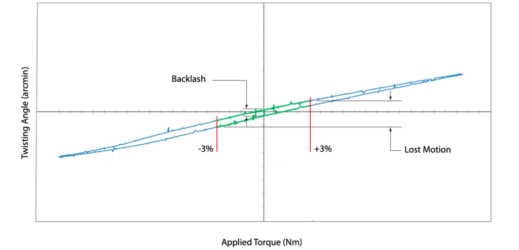
How is it determined? Similar to torsional stiffness, the gearbox is loaded with a continuously increasing torque up to the nominal torque capacity while the input shaft is locked. This is repeated in the opposite direction. The resulting twisting angle is measured at +/-3% of nominal torque (See Figure 2). However, in most cases, it is calculated for a specific torque rather than being a published value.
FIGURE 2: GEARBOX HYSTERESIS CURVE (detail at ±3% Nominal Torque)
How can I use it? Practically, total lost motion can be calculated for an application by summing lost motion due to backlash and lost motion due to torsional stiffness at a specific applied torque.
Total lost motion can be calculated for each component and summed to get the total lost motion for the system.

Angular Transmission Accuracy
What is it? The angular transmission accuracy defines the maximum transmission error (maximum amplitude of the variation) of the actual output position relative to the theoretical output position according to the ratio. It is the error during motion (as opposed to the endpoints) and looks at how close the motion is to the theoretical perfection motion. It is measured as an angle (arcsec).
How is it measured? To measure angular transmission accuracy, the gearbox is rotated without load. The input and output positions are recorded. This is done multiple times in each direction. The range of error over a full revolution of the output is the angular transmission accuracy.

How can I use it? Angular transmission accuracy becomes a factor when an application requires precision during the rotation rather than just end-to-end. For example, a gearbox rotates a part while a robot performs an operation on it. With high angular transmission accuracy, the gearbox can provide continuous coordinated motion with the robot.
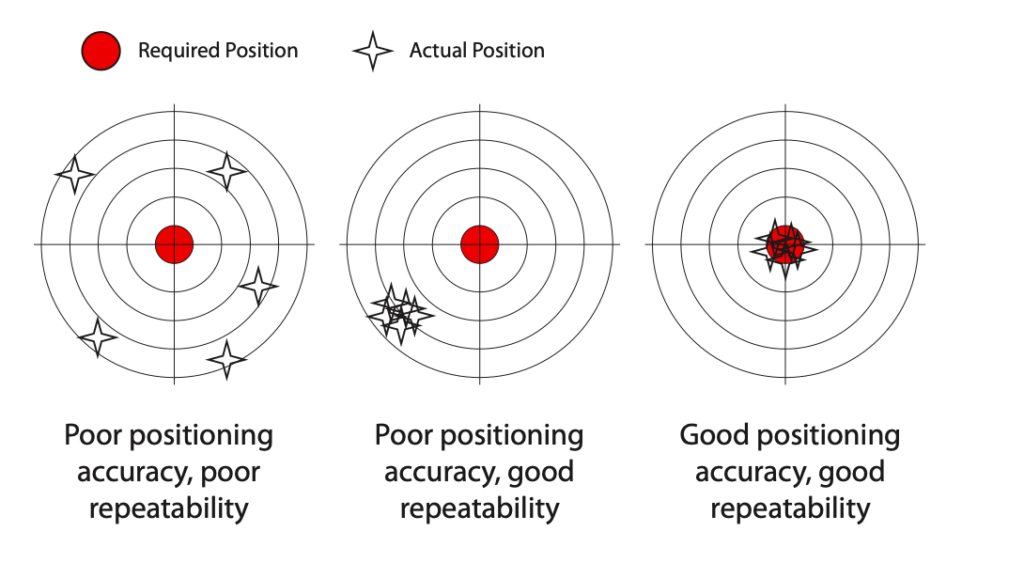
Accuracy and Repeatability
Positioning precision is determined by the accuracy and repeatability of the mechanism such as a gearbox.
Positioning Accuracy
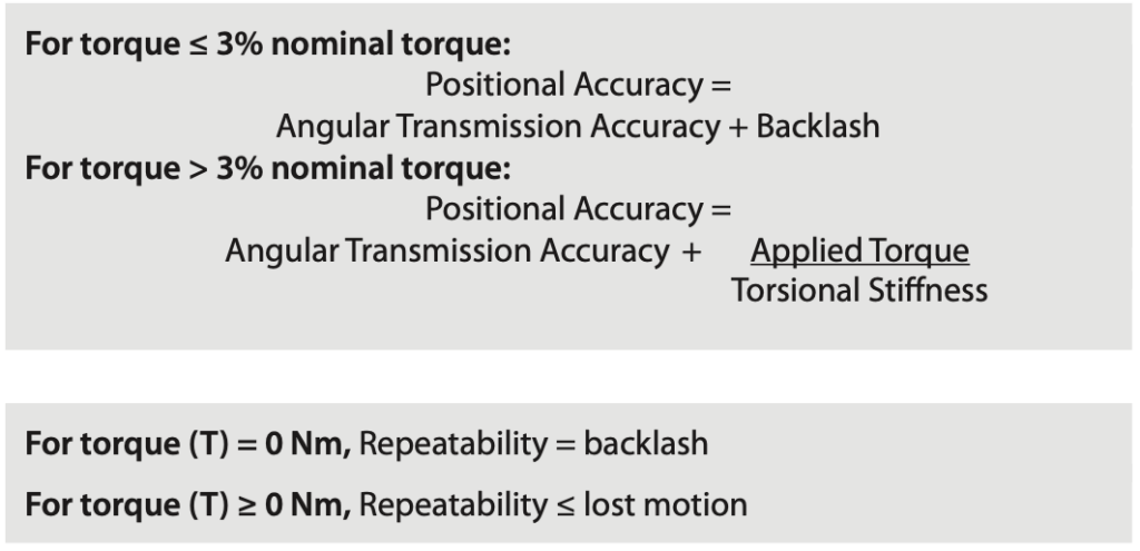
The positioning accuracy is determined by the difference between the target position and the actual position. It is influenced by angular transmission accuracy, backlash, and torsional stiffness.
Positioning Repeatability
Repeatability refers to the deviation when the gearbox is repeatedly turned to the same position under the same load. In the repeatability, the errors from the angular transmission accuracy and the torsional stiffness are constant, so that any deviation is solely the result of lost motion.
GAM
www.gamweb.com
Leave a Reply