
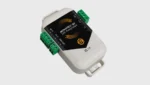
The MONITEX BT is a torque-measuring coupling hub for recording torque and speed. We have now developed a digital-to-analog converter (DAC) that makes it easy to integrate the measured signals into control systems. The DAC connects to the MONITEX BT torque sensor via Bluetooth and provides the live data as a voltage and current signal […]
Featured
Zero-Max overhung load adaptors and CD couplings for off-highway mobile equipment
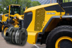
The recent trend toward electrification minimizes the power requirement needed from internal combustion engines and can sometimes even replace internal combustion engines in a driveline of Off-Highway Equipment. The result is a greener, cleaner, sustainable energy alternative. Electric motors now being designed into mobile equipment have increased the importance of integrating high-performance mechanical components like […]
Base isolation methods for earthquake-resistant construction
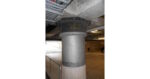
By Ringfeder Editor Earthquake-resistant construction is vital to keeping people safe and preventing economic losses in earthquake-prone regions. To ensure the safety of the public and infrastructure, it’s important to comply with all applicable earthquake codes and standards, which are consistently updated with data collected from recent earthquakes and related research. Numerous seismic standards have […]
PTDA Foundation welcoming nominations for 2024 Leadership Awards

The PTDA Foundation is seeking nominations for its Wendy B. McDonald Woman of the Year Award and Robert K. Callahan Advancing Leaders Award. The Wendy B. McDonald Woman of the Year Award celebrates a woman who, regardless of her career stage, has made significant contributions to her company and the PT/MC industry in 2023. The […]
PTDA to Host 2024 Canadian Conference

The Power Transmission Distributors Association (PTDA) will convene for the PTDA 2024 Canadian Conference in Niagara Falls, Ontario, Canada on June 4–6. Delegates in the power transmission/motion control (PT/MC) industry, representing PTDA distributor and manufacturer companies, will broaden cross-channel networks, expand connections, and deepen business relationships. “Opportunities to cultivate strong relationships between channel partners in […]
CENTAFLEX-TIR coupling saves fuel and reduces CO2 emissions for Stage V diesel engines
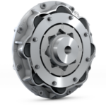
CENTA Couplings has launched a new design to reliably dampen the increased torsional vibrations from Stage V diesel engines. With its flexibility, the CENTAFLEX-TIR dual-stage torsional roller coupling helps these efficient, downsized engines achieve the lowest idling speeds, allowing end users and original equipment manufacturers (OEMs) to reduce fuel consumption and CO2 emissions in operation. […]
GAM servo coupling express service

The standard lead time for an in-stock servo coupling at GAM is five business days. However, the company understands that sometimes you may need something quicker. That is why GAM offers Express Services to get your machine up and running as quickly as possible. Same-Day Express Service: Your order ships the same day it […]
Nearly $147,000 Raised in First Stage of PTDA Foundation’s fundraising campaign
The PTDA Foundation is off to a strong fundraising start in 2024, raising nearly $147,000 during the first three months of its 2024 Fund Drive campaign. Contributions support the PTDA Foundation in empowering PT/MC (power transmission/motion control) industry employers to be more successful in their recruitment and retention efforts. “Our industry plays a crucial role […]
Torque limiters and couplings
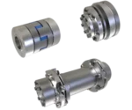
Couplings from mayr power transmission ensure reliable torque transmission and safely limit forces and torques. The shaft couplings connect shafts in the power train and compensate for misalignments. Depending on the design, they are either rigid or flexible. The mayr torque limiting clutches reliably limit torques and forces and thus prevent damage to the power […]
DATAFLEX torque measuring shaft from KTR
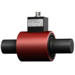
Dual-range torque sensor for measuring torque and speed Precise measuring of torque and speed is an indispensable part of modern drive technology with its variable and dynamic drives. The DATAFLEX torque sensor has two measuring ranges calculating four parameters at the same time: torque, speed, rotation angle, and rotation direction. The family of precision measuring […]