 Simple and quick assembly and disassembly, complete freedom from maintenance and wear, absolutely backlash-free power transmission: RINGFEDER Locking Assemblies are friction-locked shaft-hub connections manufactured to the highest quality standards. They are suitable for the precise fastening of all types of hubs, e.g. toothed gears, running wheels, and chain sprockets, levers, cam discs, belt and brake discs, slip-on gears, couplings or flanges, on shafts and axles.
Compared to external clamping connections, e.g. shrink discs, locking assemblies are installed between shaft and hub. By tightening the clamping screws, inner and outer rings press themselves onto the contact surfaces of the components to be connected, thus creating a friction-fit press connection. This allows not only the highest torques but also axial and radial as well as bending loads to be transmitted reliably. RINGFEDER Locking Assemblies are the superior alternative to conventional shrink-fits, wedge, keyway, or polygonal connections and offer outstanding concentricity and resistance to alternating torsion. These locking assemblies are available to users in various standard designs and sizes as well as customized special solutions
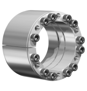
Locking Assemblies RfN 7005 Characteristics
Three-piece, self-centering, slitted locking assemblies for highest bending moments and torques. During assembly a minor axial displacement of the hub occurs. The front and rear thrust rings are separately released through release threads.
Explanations
- L = Overall width
- L1 = Overall width (without screws)
- L3 = Clamping length
- d = Inner ring diameter
- D = Outer diameter
Ringfeder
www.ringfeder.com
Leave a Reply