
Cranes and hoists are only as good as the components that make them up. One of their key components is the coupling, which is essential to maintaining uptime and enhancing the safety and reliability of your operation. Without the right coupling, your crane or hoist may not function properly, causing your manufacturing process to grind to a halt. This kind of downtime is not welcome, especially where very high loads and expensive equipment are concerned.
There are two main types of couplings that meet the demands for reliability and safety in crane and hoist applications.
BARREL COUPLINGS: HIGH LOADS, SAFE HANDLING
Hoists—which also refer to the lifting mechanism in cranes —lift and lower loads using a drum or lift-wheel, around which a rope or chain wraps. Hoists can be manually operated, as well as electrically or pneumatically driven. They can also utilize chain, fiber or wire ropes as their lifting medium. From steel mills to manufacturing plants, hoists are used in a wide range of applications that involve moving large, heavy products up and down.
A proven coupling solution for hoists, barrel couplings connect the cable drum to the gearbox output shaft and are also used in winch conveyors and platform hoists. These couplings transmit torque via barrel-shaped hardened pins that fit into semicircular machined openings on the hub and sleeve—ensuring radial forces are transmitted safely.
THE DESIGN ADVANTAGES OF BARREL COUPLINGS
The barrel coupling’s design offers several benefits compared to other toothed couplings:
- Due to the profile of the barrels and teeth, the coupling is subjected to lower bending stresses at the bottom of the teeth—improving protection against bending and radial loads.
- The larger contact surface between the barrels and teeth also allows radial loads to be better distributed, which increases the lifespan of your coupling.
- The use of high-strength materials, such as steel, increases the coupling’s transmission capability without requiring you to change the design or dimensions. As a result, you can often select a smaller coupling size for your application—leading to improvements in energy efficiency due to the lower weight and acceleration forces.
- Internal and external covers, each equipped with a lip seal, prevent foreign matter from entering and lubricant from escaping.
- A wear indicator attached to the external cover lets you check the wear and axial position of the housing relative to the hub. In addition, markings facilitate easy reassembly should you need to dismount the coupling.
CREATING A STATICALLY DETERMINATE SYSTEM
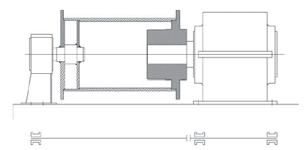
Fixing the gearbox output shaft to the cable drum creates a rigid, statically indeterminate mounting (Figure 1)—making perfect alignment and leveling critical during the assembly process. Both, however, are difficult to achieve in practice. In addition, mounting inaccuracies, structural deformation and wear in moving parts create additional forces in the gearbox output shaft. These forces occur in alternating bending loads and can lead to shaft breakage and severe damage to bearings and gears. This is where barrel couplings come into play.
Barrel couplings perform the function of an articulated joint, making the connection between the cable drum and gearbox statically determinate (Figure 2) and avoiding high bending moments. They also prevent angular and axial shaft misalignment caused by mounting inaccuracies, structural deformation and normal wear and tear. Without the flexibility provided by these couplings, the forces generated by the alternating bending loads can lead to shaft breakage and other costly, disruptive damages.
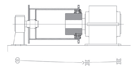
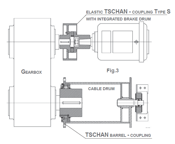
Figure 3 illustrates the mounting of a barrel coupling in a typical lifting mechanism. Because this coupling allows axial displacement, a self-adjusting bearing must be mounted—fixed laterally—at the opposite end of the drum shaft. In special applications, however, the barrel coupling can be designed as an articulated joint that withstands axial forces by itself.
HOW TO SIZE YOUR BARREL COUPLING
Sizing your barrel coupling comes down to three things: transmission torque (T), the applied radial load (F) and shaft diameter of the gearbox unit. What follows is a simplified version of the process, including some of the calculations involved at various steps:
1. Calculate the nominal transmission torque (T) based on maximum installed motor power or consumed power. This value must be less than the transmission torque (TKmax) of your selected coupling according to the datasheet.
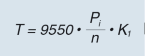 Calculating T in terms of installed motor power:
Where:
Pi = maximum installed motor power
n = rotary speed of the rope drum
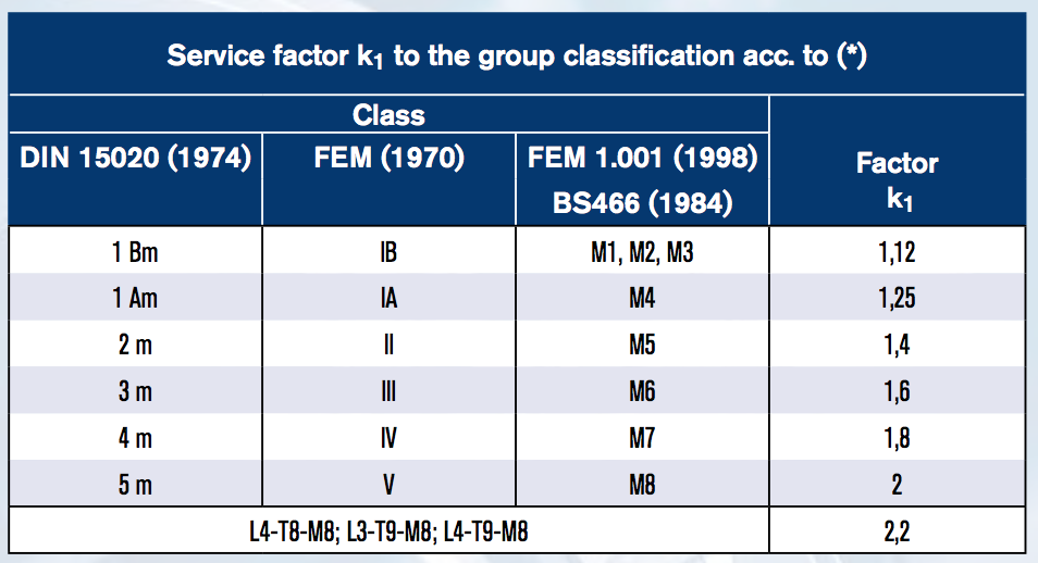
K1 = service factor (see table)
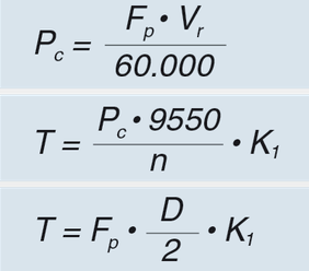
Calculating T in terms of consumed motor power:
 Where:
Pc = maximum consumed motor power
FP = drum static pull, including cable and pulley efficiency
Vr = drum cable lifting rate
n = rotary speed of the rope drum
D = drum pitch diameter
K1 = service factor
2. Calculate the applied radial load (F). The next step in the process requires you to evaluate the radial load that will act on your coupling. Radial load refers to the fraction of the load that your coupling must withstand due to the pull of the load and hoisting tackle. This calculated value must be lower than the admissible radial load (Frad) indicated in the data sheet.
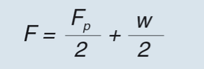
For systems with double line to drum. Where:
FP = static pull of drum, including cable and pulley efficiency
w = weight of the drum, including the rope and connected parts of the coupling
3. Verification of the geometric dimensions. Finally, make sure the diameter of your gearbox shaft is smaller than the coupling’s maximum admissible diameter (d1kmax) as indicated in the data sheet. These values are valid for shafts with keyways according to DIN 6885/1. Please contact our technical team for other types of fixing.
RINGFEDER BARREL COUPLINGS
Ringfeder barrel couplings, which support the rope drum, can handle heavy loads, as well as large amounts of torque up to 815,000 Nm—making them reliable options for hoists with very high weight limits. Other notable features include:
• Outer diameters up to 850 mm
• Large bore sizes up to 425 mm
• Built-in wear indication for easy monitoring
• Torque transmission by hardened steel rollers
• Heavy-duty material options, including cast iron (TSCHAN TK) or ductile iron (TSCHAN TKV)
Ringfeder
www.ringfeder.com
Would you like to get the history of the invention of the Barrel Type Drum Coupling? you can ask Malmedie as we innovated this concept back in the late 1950’s.
Is Ringfeder sponsoring this article? might be good to have other manufacturers listed, especially those that have designed and continue to innovate in this category