RR Fisher & Co Releases R+W Safety Couplings For Particle Measuring Systems

November 3, 2010 by  
Filed under Safety

RR Fisher & Co. Ltd. the released its ATEX certified R+W safety couplings for Sympatec’s particle measuring systems. These safety couplings offer an ATEX design with high-temperature steel plug segment.

RR Fisher Co Supplies R W Safety Couplings

Sympatec’s particle measuring systems are specifically designed to detect particles in a nano range up to 10mm. The systems identify application in quality assurance in pharmaceutical manufacturing, cement production, coffee production and print toner manufacturing.

A representative sample is first taken from the production system before measurements can be made. The materials that will be tested are conveyed on air via a production process in pipes with 50mm-800mm inside diameter.

A SK5/10/F/XX type of R+W safety coupling was used in the drive mechanism of the sampling tube. The coupling has ATEX certification for zones 2/22 and 1/21. This is important because samples are taken in an ignitable dust or explosive atmosphere.

Aside from operating and installation instructions, a required declaration of conformity and ATEX certificate is enclosed with the R+W Safety Coupling when it is delivered.

Specified by the customer, the SK5 pluggable solution is necessary for certain industrial environments where a wide variety of products are often designed on the same equipment line.

The components utilized in processing the previous products must be cleaned when converting the line for the production of a different product. Removing components for cleaning is made easy with its plug-in capability.

Another problem at this stage is about the temperature range. The range of operating temperature specified for the coupling is up to 150ºC.

Since plastic plug-in segments are rated for use up to 120ºC, the material for the said parts was changed. Built similar to the plastic part, the new steel plug design can handle an extended temperature range.

www.rrfisher.com.au

www.sympatec.com

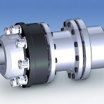
Two-Year Project Produces Safety Coupling 60-70% Lighter

October 21, 2010 by  
Filed under Safety

The German couplings specialist R+W has developed a safety clutch which, it claims, is 60–70% lighter than conventional designs, and allows smaller clutches to be used in some applications. The SL series clutch, which made its debut at the recent Motek exhibition on Germany, is the result of a two-year collaborative project with universities.

RW Clutch floating

The dramatic weight savings – which result in record ratios of torque output to weight and size – have been achieved through a combination of advanced materials and new coatings. A version with a 160Nm torque limit weighs just 370g. There are four models, with torque ratings from 5–700Nm, capable of operating at speeds of up to 10,000 rpm.

The clutches also incorporate specially designed springs and ball detent systems that are said to raise torque levels by up to 40% compared to standard safety couplings.

www.rwcouplings.com

Hybrid Coupling Combines Fluid, Electronics, Tubing and Cable

July 1, 2010 by  
Filed under Industry News

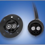
The Hybrid Connector integrates fluidics and electronics into a single connection point. Combining dual flow paths into an integral hose assembly eliminates the need for multiple connections and simplifies the user interface between modular tools, umbilicals or hand pieces and a device. Integrating high-cycle electrical contacts directly into the connector eliminates the need for a separate power cable to remote tools.

CPC Hybrid 300x270

The Hybrid Connector can simplify connections in a range of applications including diagnostic equipment, surgical tools, analytical instrumentation and hospital beds. The easy-to-use connector also can be customized for specific customer applications.

Colder Products Co.
www.colder.com

6 ways to assess torque needs for safety couplings

April 8, 2010 by  
Filed under Safety

Safety couplings that operate on the ball detent principle primarily suit disengagement torque applications. But, with some modification, they can suit highly dynamic applications with resonant frequencies and torsional rigidity. Here is a brief examination of common equations used to calculate the following torques for safety coupling design in a drive system: disengagement torque, acceleration torque, acceleration and load moment, thrust force, resonant frequency, and torsional rigidity.

Disengagement torque. The disengagement torque must be greater than routine torque moments within a drive train. First, determine torque requirements within the drive train. In practice, a multiplication factor of 1.5 times the nominal operating torque is often adequate to accommodate acceleration moments and other influencing factors. To calculate minimum torque ratings for a drive train, use the following equation:

TKN ≥ 1.5 x TAS

Where:

TKN = torque in the drive train (Nm)

TAS = Peak torque in the drive train (Nm)

Peak torque is usually taken from the rating plate on the given drive mechanism.

You can use the number 9,550 as a constant value to convert power into Nm. Thus:

TKN ≥ 9,550 x PAN/n x 1.5

Where:

PAN = Power of the driving side (kW)

n = speed (rpm)

Acceleration torque. The acceleration torque method is a more accurate technique. In addition to angular acceleration, it makes allowances for peak torque on the driving side, the mass distribution, and the moments of inertia inherent to the driving and driven ends. With the help of a correction factor (surge or load factor) established according to the machine and application, acceleration torque can be determined using this method. Normally, a distinction is made between three types of surge or load factors:

SA = 1 (harmonic strain)

SA = 2 (periodic strain)

SA = 3-4 (non-periodic strain)

The following equation reflects these relationships:

TKN ≥ α  x JL ≥ (JL/JA + JL) x TAS x SA

α = Angular acceleration (s-2)

JL = Moment of inertia on the load side (kgm2)

JA = Moment of inertia on the driving side (kgm2)

SA = Surge or load factor

Acceleration and load torque. The most accurate but complex assessment of torque for the evaluation of safety couplings is the acceleration and load torque method (start-up under load). This approach simulates an application in which constant acceleration and deceleration under load conditions takes place. Load torque is used as an additive factor to acceleration torque.

The following equation, with differentiation of individual variables, describes this relationship:

TKN ≥ a x JL + TAN ≥ [(JL/JA + JL) x (TAS – TAN) + TAN] x SA

TAN = Peak torque for the load side (Nm)

These three design methods are based on manufacturer data for the drive and the load components. In addition to torque moments, only moments of inertia and potentially incurred acceleration are included.

Thrust force. Another option for assessing application torque is the thrust force method. This method can be applied to spindle and lead screw drives as well as toothed belt drives, depending on the design of the drive system.

In addition to overall thrust force for the entire unit, thread pitch and efficiency play substantial roles in the proper design of spindle and lead screw drives. Here is the equation for the applied torque:

TAN = (s × Fv)/2000 × ∏ × η

s = thread pitch (mm)

Fv = thrust force (N)

η = efficiency

∏ = pi

If the drive and load are not linked by way of a spindle or lead screw, but by a toothed belt drive, use the following equation to calculate the incurred torque:

TAN = (d0 × Fv)/2000

d0 = pinion diameter of the toothed pulley (mm)

Resonant frequency. Each body and component in the drive train has its own natural frequency. The resonant frequency of the coupling and the entire drive system can be approximated with the following equations. A prerequisite for the calculations is the summation of mass moments of inertia of the individual components to determine the total mass moment of inertia. The torsional rigidity of the entire drive train also has a big influence on oscillation. The equation for calculating the coupling’s resonant frequency in Hz is:

ƒe = 1/2p x  √CT x ((JA + JL)/(JA x JL))

The equation for calculating the natural oscillation in speed is:

ne = 30/p x  √CT x ((JA + JL)/(JA x JL))

ƒe = resonant frequency of the system (Hz)

CT = Torsional rigidity of the coupling (Nm/rad)

ne = Natural oscillation term of the system (rpm)

Torsional rigidity. Whether a machine is designed to be rigid or damping depends on the respective application. The rigidity of all individual components, including the coupling, should always be taken into account. In theory, if a body twists by a defined angle if it is subjected to a certain load (torque). The degree of twist depends on the rigidity of the body (countering the torque). This relation is expressed:

φ= 180/p x TAS/CT

R+W America

www.rw-america.com

For safety, electronics may not be the best choice

The trend of replacing mechanical systems with electrical systems continues. Even developers of hydraulic and pneumatic systems are following it. But, as is becoming evident through the latest unintended acceleration issues, electronic components can have a few drawbacks that should not be overlooked in a design.

ST1 Lamelle

When in comes to designing a system for safety, specifically when considering whether to choose a mechanical component such as a coupling, or to go electronic, remember this: Electronic safety components have two major disadvantages compared to mechanical safety components.

  1. Reaction time. Assume a machine crashes and causes an overload. According to engineers at R+W America, a signal from the monitoring circuit does not reach the motor controller until 5 to 7 ms following a sharp increase in torque. During this period of latency, the controller attempts to further increase torque to reach the setpoint value. Most likely, another 10 ms will pass before the motor is shut off. Depending on the drive train’s moments of inertia, more time can pass before the electronics brings the whole system to a stop.
  2. Multiple potential failure sources. Electronic monitoring systems need multiple sensors for data. Between the monitoring system and all of its sensors and other components, you have a system with multiple possible points of failure.

A mechanical safety coupling, on the other hand, completely disconnects the drive from the load within 3 to 5 ms; 1/3 of the time needed by an electronic cut-off. Noted engineers at R+W America, “electronic machine monitoring is not suitable for high speeds due to the large centrifugal mass of the rotating parts.”

Also with a mechanical safety coupling, you have one component per axis, reducing the number of possible points of failure.

Safety couplings must demonstrate two clear behaviors:

  1. Upon overload, separation of drive train and load should occur within a few milliseconds.
  2. After the coupling has disengaged, residual friction should not be excessive so as not to damage coupled components that continue to be driven due to mass moments of inertia.

According to R+W, safety couplings can be subdivided into five classes:

1. Rigid safety couplings used in indirect drive applications.

2. Torsionally rigid safety couplings for use between two shafts or flanges. These couplings resist twisting and can be subdivided into two groups.

A. Single-piece torsionally rigid safety couplings.

B. Press-fit couplings.

3. Vibration-damping safety couplings are fitted with an elastomer insert that damps incurred drive vibration.

4. Economy safety couplings suit applications requiring simple overload protection and functions as a variation of the ball-detent principle.

5. Torque-limiting line shafts, which span long distances between shafts.

(Some material, courtesy of R+W America.)

Handbook for Mechanical Torque Limiters

February 17, 2009 by  
Filed under Industry News, Safety

As a part of a series of technical handbooks developed for the European manufacturing industry, R+W has released a new handbook for the design and application of safety and overload couplings.

rw handbook

Covering the very basics of what torque limiters are, the varieties available, and why they are used, all the way though complex theories and advanced sizing formulas used to determine optimum coupling selection, this handbook includes information for all levels of design engineers with a potential need for torque overload protection. This is the second of a two part series, with the first book handling the design and application of precision couplings and line shafts. Contact R+W America for more information.

www.rw-america.com