
PRECISION COUPLINGS FOR MOTION For the past 30 years or more, designers of highly dynamic servo drive systems have been turning to bellows couplings to optimize the stiffness, inertia, and smoothness of rotation in their coupling applications. When it comes to torsionally rigid couplings the stainless steel bellows win in all three categories. Take for […]
Disk
SDP/SI: new disk type flexible couplings
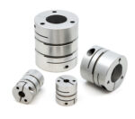
Stock Drive Products/Sterling Instrument (SDP/SI) expands their selection of flexible couplings to include the single disk type couplings (short type), series S50XHSM… and the double disk type couplings (standard length type), series S50XHWM… The disk-type flexible couplings are an economical option while providing greater torque capability and improved performance in a reduced size. The compact […]
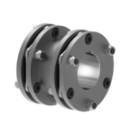
Vulkan DISCFLEX DNZ-A disc coupling

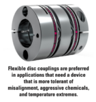
The DISCFLEX is a disc pack-type coupling suitable for demanding industrial applications. The torque is transmitted through the coupling by means of tension and compression of the high-strength stainless steel flexible disc elements. High rotational speeds and high torque capacity within a small, lightweight package are major advantages of this product. In addition, the DISCFLEX […]
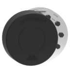
Vulkan DISCFLEX DNZ-G disc coupling
The DISCFLEX couplings are suitable for miscellaneous industrial applications, in which the torque is transmitted from the input shaft to the output shaft by means of alternate traction and compression of the elastic element. High rotational speed and torque transmission capacity within limited dimensions and weight are the major advantages of this product, together with […]
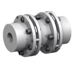
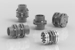
Vulkan DISCFLEX disc pack type coupling
Nominal Torque Range 153 Nm – 660000 Nm The DISCFLEX is a disc pack type coupling suitable for demanding industrial applications. The torque is transmitted through the coupling by means of tension and compression of the high-strength stainless steel flexible disc elements. High rotational speeds and high torque capacity within a small, lightweight package are […]
Steel disc couplings TND VDV
Torsionally rigid, absolutely backlash-free steel disc couplings of the new series RINGFEDER TND – originating from the proven TSCHAN, POSIMIN, and GERWAH series — are suitable for the most diverse applications and particularly ideal for all drive tasks requiring freedom from wear and maintenance as well as excellent misalignment compensation and positioning accuracy. The characteristic […]
Ringfeder shrink discs safety covers
Specially developed and designed for shrink discs of the three-part series RINGFEDER RfN 4061 as well as the two-part series RINGFEDER RfN 4161, original RINGFEDER Safety Covers provide reliable and safe contact protection against screw heads of rotating shrink discs. They are made of high-quality black synthetic material, which features outstanding tear and abrasion resistance […]
TND Steel Disc Couplings with updated design for drive applications
Edited by Mike Santora Ringfeder recently updated its TND Series of steel disc couplings, which feature backlash-free torque transmission and excellent positioning accuracy in machines that involve synchronous operation, frequent starts, and stops or reversing operations. Typical drive applications include printing and packaging machines, compressors, pumps, and variable speed drives. Using in-depth finite element analysis […]
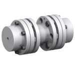
Disc couplings for test, measurement, and inspection systems
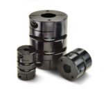
Ruland disc couplings are zero-backlash, have high torque and torsional stiffness, and can accommodate all forms of misalignment, making them well suited to the requirements of test, measurement, and inspection systems. Single and double disc styles are available, allowing the designer to tailor coupling performance to application requirements. Disc couplings are comprised of two anodized […]
Ringfeder’s TND steel disc couplings with updated design

RINGFEDER announces an updated version of its proven TND Series of steel disc couplings, which feature backlash-free torque transmission and excellent positioning accuracy in machines that involve synchronous operation, frequent starts, and stops or reversing operations. Typical drive applications include printing and packaging machines, compressors, pumps, and variable speed drives. Using in-depth finite element analysis […]