Here we address considerations when specifying servo couplings to satisfy servo requirements — ever-evolving specifications that become more demanding all the time.
By Tetsuya Niwa • Director of product planning and development
Kei Yamada • Product Manager — Product planning and development
Hiroki Goto • engineering specialist
Paulo Castelo • Technical solutions supervisor • NBK America
Flexible couplings fasten machine drive shafts and transmit torque while allowing for multiple forms of misalignment such as lateral, angular, and axial. Various flexible-coupling types have been developed to satisfy application demands.
Case in point: Couplings used in servo systems with feedback mechanisms are often selected for their static torsional stiffness and backlash-free features — integral requirements for high-precision and high-speed applications. Here, design engineers often select disc couplings for their static torsional-stiffness. But new technological improvements in servomotors have spurred dramatic improvement in speed response frequency. The catch is that vibration (also called hunting) tends to arise when designers apply increased gain settings to servo systems and use high-static-torsional-stiffness couplings such as disc or bellows-type couplings.

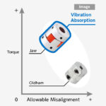
One way to resolve hunting in servo systems under high gain settings is to use couplings with vibration-damping technology. As we’ll explore, high-gain rubber couplings in particular excel in servo systems for semiconductor-manufacturing equipment and other precision automation — which are systems that need to have high response.


Stabilization time — and its effect on productivity
Integrated damping in couplings can dramatically reduce stabilization time — and that in turn increases machine-axis speed and general productivity.
Just consider the interplay between a feed-screw machine, ball screw, and servomotor system. For feed-screw applications that use both servomotors and ball screws, ideally the operation proceeds in exact accordance with servomotor commands. But real-world setups often see delayed execution of commands — a factor in errant positioning called stabilization time.
Higher servomotor gain and high-response operation are needed to minimize stabilization time — but substantial gain increases actually spur the counterproductive phenomenon of hunting. This hunting effectively distorts machine-operating equilibrium and hampers servomotor control. So increasing gain while suppressing hunting requires systematic adjustments to servomotor parameters — including mechanical coupling characteristics.


Tests show when a servomotor drives a design through a disc or bellows coupling, raising the gain tends to readily cause hunting. So here, the conventional approach is to switch to a coupling with higher torsional stiffness as a way to boost the entire rotating axis’ rigidity. However, whole-system torsional rigidity depends on torsional rigidity of the ball screw.


The table in this feature titled, “Torsional rigidity of the entire system” shows calculated torsional-rigidity values for a complete example system incorporating various couplings.
| Torsional rigidity of the entire system | Disc coupling | High-gain rubber coupling |
| Torsional rigidity of coupling: Kc
(N·m/rad) |
450 | 240 |
| Ball screw groove diameter in mm | 7.8 | 7.8 |
| Support bearing – Nut distance (mm) | 300 | 300 |
| Torsional rigidity of ball screw Kbs in N·m/rad | 96 | 96 |
| Torsional rigidity of entire system K in N·m/rad | 79 | 68 |
Torsional rigidity of the entire system is 1/K = 1/Kc + 1/Kbs.
The torsional-rigidity value of the disc coupling in this example setup is 450 N·m/rad compared to a high-gain rubber type coupling value of 240 N·m/rad. Only examining these values, one would conclude that disc couplings have 1.9 times higher torsional-stiffness values. In fact, total-system torsional rigidity is 79 N·m/rad for the former and 68 N.m/rad for the latter — so the actual difference is only about 1.2 times.


In fact, the torsional rigidity of the ball screw is the more dominant determining factor affecting system torsional rigidity — not the coupling.
That means simply changing the coupling to one with inherently higher torsional stiffness values may insufficiently improve system torsional rigidity … and may not protect against hunting, either. But technical advancements in servomotors (especially in response-frequency speed) have increased the need for vibration damping (as a way to avoid hunting). Ultimately, vibration damping plus adequate torsional stiffness allows for accurate position repeatability — especially useful on axes for positioning.

In fact, we conducted extensive tests to verify the relationship between a coupling’s static torsional stiffness and the positioning repeatability of an actuator.
The testing methodology we detail in this feature adheres to JIS B 6192 protocols; the testing equipment included three different coupling types from the manufacturer. Stop-position accuracy was measured seven times. Then spreads between maximum and minimum values were calculated and respective values compared and reported in test results. Refer to the charts that accompany this feature for those. The origin of position is set at both the center and edge for the maximum-range linear stroke. Maximum values as testing parameters are expressed as ± values.
| Equipment in test setup | Part numbers | Manufacturer | Note |
| Actuator | KR30H | THK | Positioning repeatability to ±0.005 mm |
| Position accuracy to 0.1 mm | |||
| Motor | HF-KP013 | Mitsubishi Electric | |
| Coupling | XGT-25C-6×8 | NBK | Static torsional stiffness: 170 Nm/rad |
| XBW-25C2-6×8 | NBK | Static torsional stiffness: 850 Nm/rad | |
| MJT-20C-RD-6×8 | NBK | Static torsional stiffness: 55 Nm/rad | |
| Laser displacement sensors | XL-80 | RENISHAW |
The test equipment detailed in this feature used NBK America XGT high-gain rubber-type couplings; XBW disc-type couplings; and flexible couplings from a discontinued line of MJT products. Accuracy of stop position was measured seven times.
Notice from the test results that static torsional stiffness doesn’t gravely impact positioning repeatability on actuators. In fact, the sub-micrometer variations that we reference in our results likely arise from the actuator’s precision limitations.


| Testing conditions for one motion axis | |
| Motor speed | 3,000 rpm |
| Acceleration deceleration | 50 msec |
| Positioning location | 20,170,350 mm |
| Loaded object | 3 kg |
High-gain rubber servo coupling construction
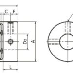
High-gain rubber couplings — those with hydrogenated nitrile butyl rubber (HNBR) — have an integrated structure that includes aluminum hubs on both sides molded with a vibration-reduction rubber that prevents backlash — yet remains flexible. An internal claw-like structure lined with HNBR optimizes torsional rigidity and damping.


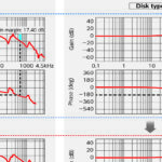
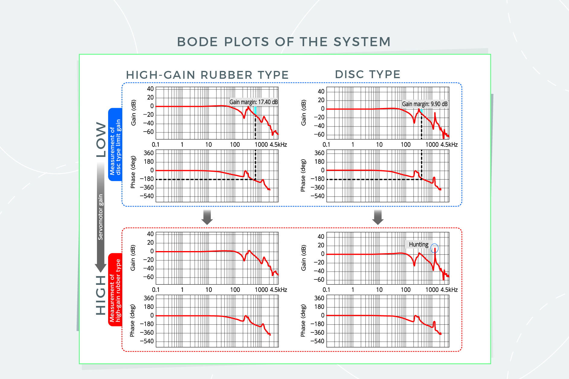
Bode plots illustrate why high-gain rubber couplings increase servomotor gain well beyond the capacity of comparable disc couplings with higher torsional stiffness values. Gain width between 0 dB and the point at which there’s a phase delay in the Bode plot is -180° — and this is called the gain margin. General guidelines for servo systems recommend gain margins between 10 and 20 dB. As the servomotor gain is increased, gain margin decreases. When the gain margin falls below 10 dB, hunting tends to occur.


Compare the limit gain (which is the servo gain at which hunting occurs) of the disc-type coupling to the gain margin of the high-gain rubber-type coupling. Notice that the high-gain rubber-type coupling at 17.40 dB surpasses the disc-type coupling’s 9.90 dB value. Because the gain margin is above 10 dB, the servomotor gain of the high-gain rubber type can exceed that for the disc coupling — thus shortening stabilization time and increasing throughput.


The table titled, “Difference in stabilization time according to coupling type and servomotor gain” shows stabilization-time deviations by coupling type and servomotor gain. If servomotor gains are equal, there’s no difference in the stabilization time due to the difference in couplings. However, when comparing the servomotor limit gain, stabilization time is 12 msec for the disc-type limit gain (25) and 3 msec for the high-gain rubber-type limit gain (32). High-gain rubber types that suppresses hunting and improve servomotor gain more effectively minimize stabilization time.
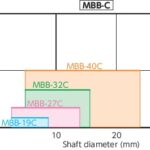
We performed additional testing on an actual system including an axis running off a ball screw with a shaft diameter of 15 mm and a 100-W servomotor. The test was run with the motor at 3,000 rpm; the acceleration and deceleration time was 50 msec; workpiece load was 3.0 kg; and the ratio of moment of inertia of load: 3.5. Refer to the tables for specific results.


| Stabilization time by coupling type and servomotor gain | ||
| Servomotor gain | Disc coupling | High-gain rubber coupling |
| 25 | 12 msec | 12 msec |
| 32 | Occurrence of hunting | 3 msec |
In short, rubber has durability … and rubber as a subcomponent in couplings effectively imparts damping properties. Data on the material’s durability has accumulated since the advent of high-gain couplings in 2007. Plots of torque versus angle show that even after 108 drive tests, there’s no degradation of performance due to rubber deterioration in couplings that include the material.
Know that in the future, servomotors will need ever-higher frequency response — along with demand for higher precision and higher speed. So industry will continue demanding coupling technology that melds high torsional rigidity and high-level damping properties to maintain peak servo-system performance. For more information, refer to Atsushi Matsubara’s 2008 piece, “Design and Control of Precision Positioning and Feed Drive Systems” and Nabeya Bi-tech Kaisha technical data in the 2017 NBK General Catalog.

NBK America | nbk1560.com/en-us