
Couplings connect rotating shafts in equipment powered by electric motors and other drives. All transmit torque and angular velocity. Flexible variations compensate for misalignment. Many of the latter even address vibration and improve system dynamics.
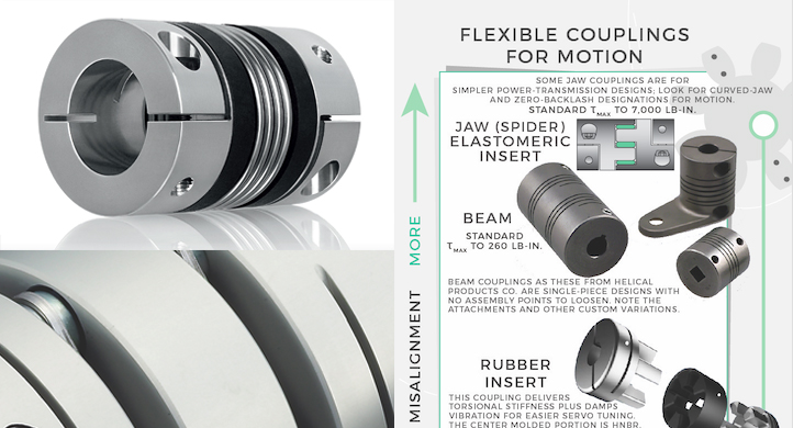
Design considerations include machine or installation construction and backlash, torsional stiffness, damping, inertia, torque ratings, maximum rpm, size, misalignments, ease of installation, robustness, and cost. For power transmission (as in motors for pumps and large material-handling setups) common choices are gear, disc, elastomeric tire, grid, jaw, and Oldham couplings because of their ruggedness and ability to transmit very large torques. Motion-control applications (as for axes employed in precise positioning of loads, for example) typically employ couplings capable of often-more modest but far more precise torque transmission. These include curved-jaw, beam (slit), bellows, disc, and other zero-backlash couplings.
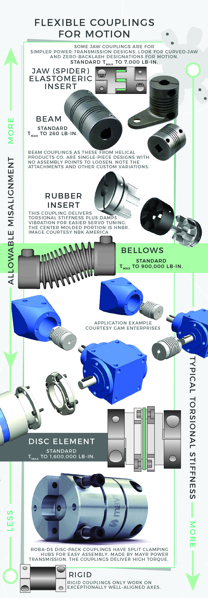
As we’ll explore, any misalignment that couplings accommodate should be what’s otherwise unavoidable even after proper machine-axis squaring and installation adjustments. That’s because misalignment — manifest as parallel, axial, and angular misalignment— degrades efficiency, induces bearing wear, and excites machine natural frequencies. To review, the maximum amount of angular misalignment for which a coupling can compensate is expressed in degrees; parallel misalignment between the shafts a coupling connects is expressed in inches or millimeters. Axial misalignment is also a length value; it’s the maximum permissible spread between coupled shafts — and in fact, a misalignment permutation often most affected by thermal effects. Flexible couplings for motion control are often less forgiving of misalignment than those for more straightforward power transmission, and resolve it with specialty design features.

A related phenomenon and a coupling consideration specific to motion-control installations is backlash. In applications for strict power transmission, backlash is far less of a concern than that of efficient torque transmission — and actually a characteristic that (in normal moderate quantities) helps make some couplings in these settings more efficient and forgiving of misalignment. In contrast, couplings on the outputs of steppers and servomotors are designed to prevent the lost motion that can degrade output-product quality or overall machine throughput.
Note there’s a difference between backlash (which is true mechanical clearance) and the torsional deflection or windup that all loaded rotary components exhibit. Most couplings for motion applications are inherently backlash free or preloaded to eliminate backlash — but they all have different torsional stiffnesses, which is sometimes a tradeoff for lateral flexibility.

Pitfalls to avoid during selection of flexible couplings for motion
Design engineers often run into trouble when they neglect to account for environmental effects on couplings — particularly flexible couplings installed in gritty or caustic areas, vacuum environments, or places that are extremely hot or cold. Beyond that and the common design considerations already listed, designers must account for dynamic forces to which a coupling will be subject. Steer clear of using published an axis’ gearset or motor peak-torque values for setting its coupling’s nominal torque rating. That’s because this approach usually makes for an assembly with an oversized coupling and an unnecessary inertial increase.
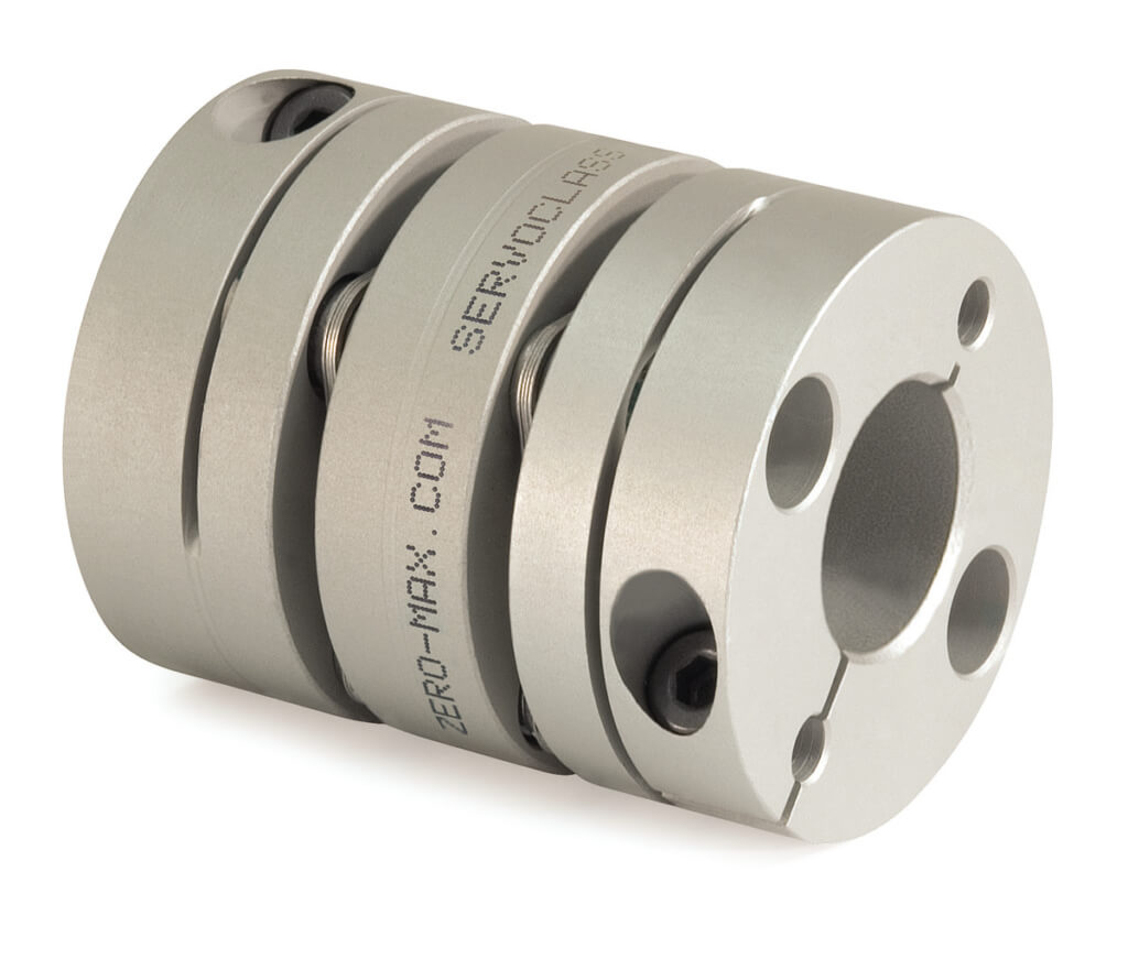
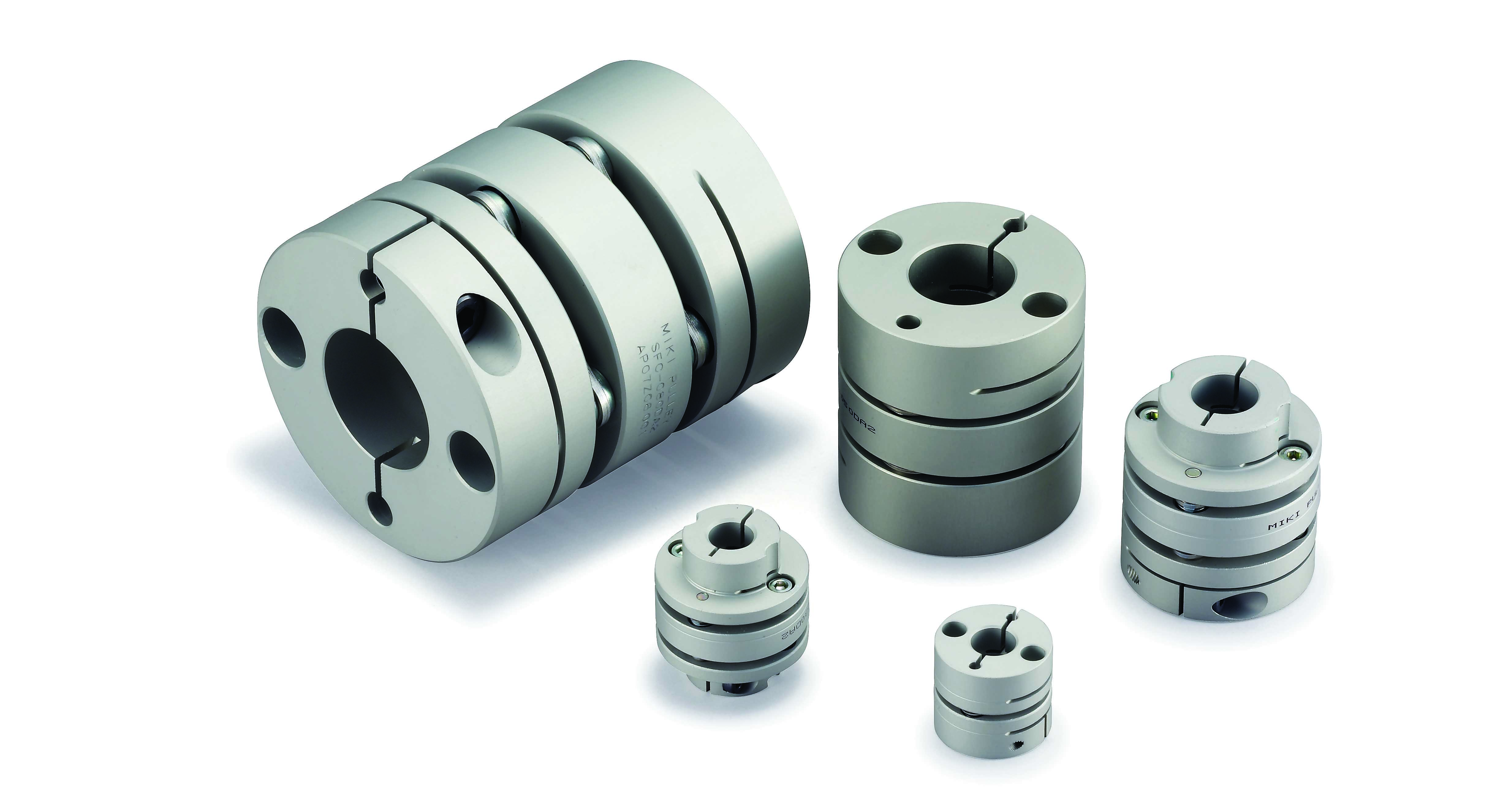
Designers should also avoid the application of a coupling type simply because it’s a familiar technology. For example, beam couplings are extremely well known in industry, and they excel on axes transmitting moderate to light torque — as on leadscrew-driven motorized axes or where there’s a need for attachment of a precision encoder, for example. However, some particularly demanding designs may necessitate a flexible coupling type that maintains higher torsional stiffness.
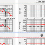
On the other hand, it’s also unadvisable to simply pick a coupling based on high torsional stiffness. Many flexible couplings have an inherent stiffness that exceeds application requirements for servo tuning and motion accuracy. Even in motion designs requiring high stiffness for the shortest possible response time (as in equipment for electronics manufacturing, for example) couplings with good damping characteristics often offer more effective optimization than more torsional stiffness. (Refer to the section, “When motion designs need torsional stiffness — as well as damping” at the end of this section for information on this topic.) That’s because overly stiff couplings of many designs pose an unnecessary risk of fatigue.
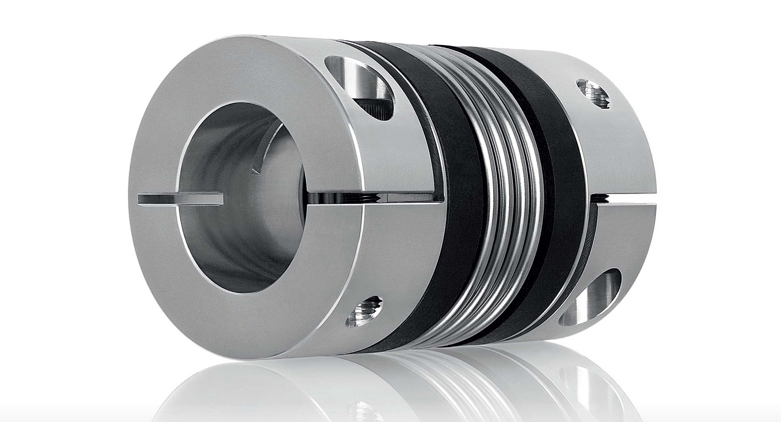
Understanding flexible-coupling torsional rigidity: Bellows-coupling example
Torsional rigidity is an object’s resistance to torsion or twisting under applied torque. Torsional rigidity in couplings is torque per value of angular displacement, and it’s a value that affects overall machine design. Even slight variations degrade positioning accuracy and limit cycle speeds. Consider the case of bellows couplings and the specifics of how their moderately high torsional stiffness is verified and expressed:
Torsional stiffness Ct (in N·m/rad) = M/ѱ — where M = Torque, N·m and ѱ = Angular displacement, rad. Applied mass at an industry-set moment arm gives torque M = mgR, where m = mass, kg; R = Moment arm; g = Gravitational acceleration (9.81 m/sec2); and m = 0.38 m.

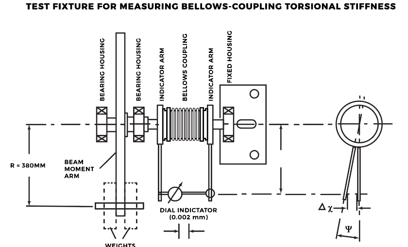
Angular displacement Δx from a test-setup dial indicator = Indicator reading (mm); τ = Indicator moment arm (mm); tan (ѱ) = Dx/ τ as noted in the illustration showing a typical fixture for measuring bellows-coupling torsional stiffness. Also — ѱ = arctan (Dx/ τ), degrees. So torsional stiffness in N·m/rad is Ct = M/ѱ (Nm/deg) = M·180/π · ѱ.
It’s usually unnecessary and impractical to test all components in design, which is why engineers use theoretical system-stiffness values. One caveat here related to couplings is that different manufacturers’ coupling-stiffness ratings vary with measurement methods. There can also be differences between published and measured values. Two tips from Mike Parzych of GAM Enterprises on this: Use caution when designing a motion machinery relying heavily on overall stiffness for good design performance. Also, look for evaluations that faithfully model performance characteristics to ensure stiffness and machine-assembly performance.
In fact, the most suitable coupling choice ultimately depends on application requirements and machine throughput. If improving axis positioning and cycle time is priority, focus on boosting powertrain stiffness. Selecting couplings with high torsional rigidity (among other things) can minimize lost motion from torsional windup. Shorter couplings or those with reinforced bellows can boost torsional rigidity values … But keep in mind that while a shorter coupling has higher rigidity (to 60 to 70%) misalignment compensation capabilities also decrease with length.
Alignment before flexible-coupling installation: Its importance cannot be overstated
No coupling — no matter how engineered — can correct for shafts that are excessively misaligned. The nature of flexible couplings occasionally misleads design engineers and assembly personnel (or more often, end users) into believing that they’re a fix-all for compromised or less exacting machine builds. But flexible couplings put into designs with excessive misalignment exhibit material stresses and fatigue and premature failure.

Though coupling failures do occasionally originate from couplings themselves, it’s far more common that coupling issues arise as a symptom of other design problems. If a motion design does exhibit coupling problems, avoid the temptation to simply upsize or upgrade that coupling. Such upgrades are often unnecessarily expensive and short-lived solutions that actually put system bearings as well as gearing and connected motors at risk of collateral damage. Instead, make a holistic analysis of the design and consult the coupling manufacturer for assistance.
Note that when motion systems exhibit coupling issues long after a proper installation and run of service, it’s sometimes a result of some other change in the drive assembly. Even small changes to the motor, drive, or programming can be to blame — especially if a new motion sequence demands higher transmission of motor torque or the elimination of a previously held electronic limitation.
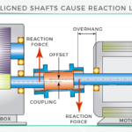
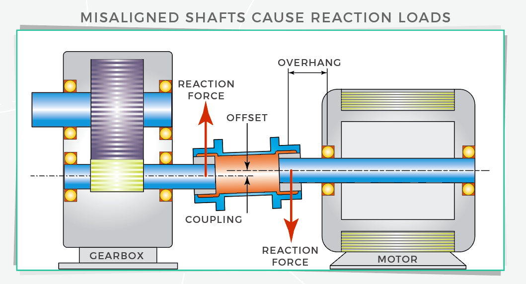
What are reaction forces?
Flexible couplings compensating for misalignment cause reaction forces … forces that in turn transmit to supporting bearings and connected shafts. We cover this topic in detail in the couplingtips.com FAQ: Reaction forces from couplings: How to prevent or mitigate? Two points to keep in mind are that reaction forces aren’t usually an issue … but if a design engineer does indeed anticipate excessive misalignment, he or she should consult with coupling manufacturers to identify coupling types to resolve the misalignment without inducing unacceptable reaction forces.
When motion designs need torsional stiffness — as well as damping
As mentioned in a recent couplingtips.com piece — New ways to use flexible couplings to minimize hunting and boost system stability — servomotor design improvements of recent years have spurred dramatic improvements in response frequencies … and that’s necessitated some unique damping functions in their motion assemblies to address the vibration (and hunting) that arise when designers apply high gain settings. Read the piece for a snippet of how disc and bellows-type couplings compare to couplings with hydrogenated nitrile butyl rubber (HNBR) center elements. Called high-gain rubber couplings, these have slightly less torsional stiffness than other options, but excel in servo designs.