


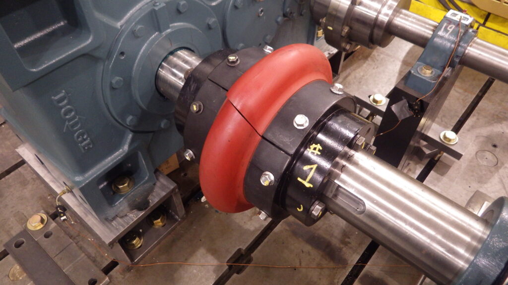

In engineering, one of the more common questions ABB gets on the Raptor coupling deals with the twisting of the element. Many users incorrectly assume this is a sign of failure. This phenomenon is common to any elastomeric coupling and is the result of a process called creep. Here, we take a look at several examples of creep.
Creep is the tendency of a material, subject to mechanical stress, to plastically deform over time. Creep can occur at any stress level, even below the yield strength of the material. Creep can occur due to compressive, tensile, and shear stresses. The level of creep is based primarily on the material, level of stress, temperature, and time. This article will discuss the mechanism and stages of creep, the effects of creep on elastomeric couplings, and the primary failure mode due to creep.
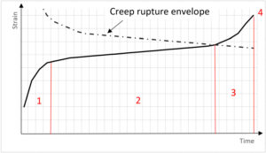
There are four stages of mechanical creep. Figure 2a illustrates the four stages for a given material and applied level of stress as a function of strain (twist) versus time. Stage 1 is called primary creep and involves a high rate of strain. During this stage, the material begins to work-harden, and the strain rate begins to reduce. In stage 2, the rate of strain begins to level out. Stage 3 occurs when the material begins to neck, and the stain rate rapidly increases. The creep rupture envelope, illustrated by the dashed line in the figure, represents the beginning of stage 3, at which point failure becomes inevitable. Stage 4 is actual failure. Figure 2b illustrates creep at a lower level of strain. Notice that most strain occurs over a short period, and the strain curve does not cross the creep rupture envelope.

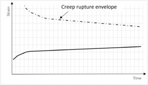

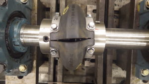
With elastomeric couplings, creep means progressive wind up, or torsional strain, when the element is exposed to constant torque or shock loading for extended periods. If the coupling is designed and sized appropriately, the stress level in the material will be low, and the amount of creep will be minimal. Figure 2b, above, represents the creep associated with an appropriately sized coupling. This coupling would likely never fail due to creep. Under higher stress levels, the element would continue to creep until creep rupture. The image below shows a Raptor coupling subject to excessive torque and misalignment for an extended period. The amount of creep before rupture can be seen in the misalignment of the split in the element.

This Raptor coupling uses a natural rubber element. This results in many benefits over couplings that use urethane, such as lower operating temperatures, lower reaction forces on connected equipment, better dampening, easier installation, etc. However, natural rubber is softer than the urethane used in some other couplings. The result is more creep under identical loading.
Creep is heavily influenced by temperature. Nearly any material will exhibit some degree of creep under constant stress, particularly as the material approaches its melting point. Any situation that leads to increased temperature will increase the rate of creep. In elastomeric couplings, that means not only ambient temperature but things like vibration, misalignment, and shock loads, all of which lead to increased element temperature. Here, the choice of coupling material can have a significant impact. Natural rubber has a relatively high thermal conductivity, allowing it to dissipate any heat generated better than other coupling materials, like urethane.
Creep occurs when a material is subjected to constant stress over a long period. With properly selected elastomeric couplings, most of the creep will occur early in the lifecycle of the coupling. This should not be considered a sign of failure or a sign that the coupling will eventually fail due to creep.