


By Zak Khan
The angle of twist on a line shaft involves its geometry, and the torque applied to it. Engineers use this calculation to determine the rotational displacement of a shaft given a certain load. The angle of twist calculations also involve determining the second area moment of inertia of a shaft. Engineers usually find these in a table of equations given a shaft’s shape and whether it is hollow or solid. Many sources provide these tables of equations, including design guidebooks and manufacturers.
It is usually best to work on an example problem to illustrate the concept behind this calculation. Say a shaft is solid and has a 70 mm diameter and is 2.0 m long. It is subjected to a torque from the system of 1500 Nm.
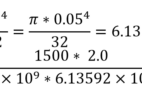
To solve, consider the important values. The diameter, D = 0.05 m, the shaft’s length, L = 2.0 m and the torque, T = 1500 nM. Additionally, J, the second area moment needs to be calculated using equations found in documentation or standard charts. Beyond this, the calculations need the modulus of rigidity of the material that makes up the shaft. This varies depending on the material, and the values of G for many kinds of materials can again be found in charts in design handbooks and from manufacturers. For this situation, assume G = 90 Gpa. Note that G is also the shear stress, τ, divided by the shear strain, γ, or τ/γ.
So for this situation,

Therefore, θ, the angle of twist is 0.0543 radians or 3.111 degrees. Performing these calculations using the torque in the system being designed is necessary to determine the angle of twist for those conditions. Make sure to look up the correct equations for J depending on the type of shaft and for G depending on the type of material.