
Updated October 2019 by Lisa Eitel || Zero-backlash jaw couplings are suitable for an array of applications. Here, Bobby Watkins of Ruland Manufacturing sheds some insight on their benefits and drawbacks.
Zero backlash jaw couplings are our fastest growing product over the last 10 years. They’ve got some great characteristics under the right circumstances. There are two types of jaw couplings:
• Standard industrial jaw couplings have a spider with straight jaws. That makes for a bit of a loose fit into the hub to allow assembly … but even turning by hand induces some noticeable slop. Standard industrial jaw couplings are a good choice for many applications — as long as you’re not positioning with them.
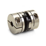
• Zero-backlash jaw couplings (which is what we manufacture) include spider arms with a profile to them … and it’s an actual press fit so there’s no clearance between the spider arms and the jaws on the hop.
In fact, some of the largest zero-backlash jaw couplings maintain zero backlash with a heavy press fit … sometimes requiring assembly with precision press equipment. Despite more challenging assembly, large zero-backlash jaw couplings benefit assemblies by preventing any lost motion in the coupling.
In contrast, smaller zero-backlash jaw couplings go together by hand pretty easily … but again, the benefits of zero backlash jaw couplings is that the three-piece design allows for a highly customizable coupling.
Going from inch to metric? Have quick reversals? No worries
There are multiple spider materials to match jaw couplings to application needs. Consider how standard jaw couplings deftly handle shock loads. If the application at hand has a very aggressive move profile requiring the coupled axis to quickly start and stop, a rigid coupling (or one without cushioning or damping characteristics — such as a zero-backlash jaw coupling) will transmit that shock and can actually accelerate the destruction of the assembly’s bearings on the ballscrew input or motor.
In contrast, compliant jaw couplings handle shock loads quite well — even on axes with frequent stops and starts to maintain high throughput. Here, requiring that the axis decelerate more gently or run softened move profiles just to accommodate a bellows coupling or a rigid coupling is unacceptable. Jaw couplings here impart excellent protection for the life of the design’s motor or actuator — and lets the axis run aggressive move profiles without sustaining damage.
Spider materials and spider hardnesses abound. For example, there’s 98 Shore A, 92 Shore A, and 85 Shore A — sometimes more casually expressed as just 85 durometer. Depending on the amount of cushioning or damping the axis needs, design engineers can fine tune the coupling behavior to suit by strategically choosing from these different spider materials.
Jaw couplings are an inherently fail-safe design
If the jaw coupling’s spider is catastrophically damaged, its arms tear off … and the coupling will go metal-to-metal and still drive. This is useful on applications where it’s important to have a fail-safe design or a positive drive. Even zero-backlash jaw couplings work in this manner. Case in point: The vertical (Z axis) of a semiconductor handling machine might be responsible for lifting and lowering an expensive boat of wafers for wafer processing. Here, suddenly dropping the valuable load could be an expensive error. So to prevent dropping that load in case of failure (and having the screw back drive) a jaw coupling here will act as the positive drive.
Jaw coupling drawbacks
One drawback of jaw couplings is that they have fairly low misalignment capabilities … so require requires precision alignment at installation. They do impart a bit of forgiveness, but nothing like beam couplings or other couplings. So if an axis’s halves are misaligned beyond what the jaw coupling is capable of accommodating, that coupling’s will hubs will go in sheer, and the spider will degrade … which in turn results in high bearing loads.
Jaw couplings excel in high-torque high-shock applications, but they are not forgiving of misalignment.
That’s especially true if the spider fails. If this occurs while the system is still running, the assembly will run though a metal-to-metal coupling engagement — potentially outputting bad product until it’s discovered the coupling’s spider has disintegrated.
Jaw couplings for electrical isolation
Jaw couplings do impart a modest level of electrical isolation that is sufficient for low-voltage applications. That’s because spider (made of polyurethane or some polymer) prevents the coupling’s metal jaws from touching the face of the hub on the other side. Manufacturers don’t usually recommend jaw couplings for electrically isolating high-voltage applications.
In fact, preventing low-voltage signals from jumping over the coupling (and potentially interfering with processes by traveling into other components) is possible with jaw couplings, oldham couplings, and disc couplings with non-metallic center members.
For more information, visit www.ruland.com.
Leave a Reply