


Selecting the couplings for your motion system doesn’t exactly stretch the limits of your engineering degree. Which is exactly why most of us don’t dig deeper to see if we’re making the best choice. The following is from a presentation on coupling selection best practices from two leading industry experts. Randy Kingsbury, Vice President of Sales and Marketing for Helical Products Company and Robert Collins, Technical Sales Engineer at Servometer, show us how to separate a good coupling choice, from the best one. Design World magazine editor Mike Santora moderates:
Santora:
Hello and thank you everyone for attending today’s webinar on proper coupling selection brought to you by Design World magazine. Without further ado, I will not turn it over to our first presenter, Randy Kingsbury.
Kingsbury: What I’m going to do is share a little bit of what I learned through my 27 years in the applications engineering group. Consider the coupling a part of your design for your system early on. You can’t believe how many phone calls we would have from people that would say, “I have this system. Everything’s great. I’m hooking this motor to this shaft. I can do that…” We say, “No problem. We can solve that.” Then, they come back and say, “Well, I also need it in stock and it needs to be delivered in the next three days because I forgot to plan for a coupling.” With that said, please remember. Put it together, think about the coupling in the beginning, not as an afterthought when you’re assembling.
There might be a few points that I’ll bring up that are specific to Helical Products and our designs here but I do want to say that there many types of couplings. All of them have their benefit. All of them have some type of limitation. I would say that there is no “perfect” coupling that is the perfect answer for every application. Much of it comes down to researching the best coupling for your application when that time comes.
These couplings come in a variety of misalignments, torque capacities. The dimensions are all over the map. Some of them are very large in diameter for the amount of torque that they’re transmitting and then some of them are relatively small. I’ll touch a little bit on materials later and give you some points to really think about as you’re working on a new design and you need to consider material options.
One point to remember when you’re selecting a coupling: there’s no governing body for couplings in how they’re rated. It’s not like the system that NEMA has for classifying motors and that type of thing. It’s a best estimate or best calculation or the results of testing from each of the manufacturers.
When you’re looking at the specifications for a coupling, make sure to read the data carefully. For example, one manufacture might list a torque rating and when you look at the footnotes, their torque rating is for static torque. Then you have another company like Helical Products where we use dynamic torque, where we’re rating our couplings based upon a high-cycle environment. We actually de-rate the coupling torque capacity based upon realizing that they’re going to be going through millions and millions of revolutions. That’s just a note to keep in mind as you’re researching the different coupling. When an engineer is going into their coupling design specifications, these are some of the points that usually they’re pretty clear on. They know the shaft diameters, whether they’re connecting a motor to a lead screw or ball screw or some sort of positioning device or a pump shaft or something like that. They’ve usually selected those components ahead of time before they get to the coupling.
They key is, when they’re sizing their coupling or determining what size coupling they need, they’ll be looking at torque. If an engineer is working with a positioning-type application, motion control, they’ll also be thinking about what kind of torsional flexibility or torsional stiffness they need in their application. That will be a factor that they usually have some idea about. In a little bit, I’m going to give you some more factors to consider when you’re looking at torsional flexibility that maybe you haven’t thought about.
When you’re coming up with a design, you have to remember to consider worst case scenarios for all of your tolerances and what is the most amount of misalignment you could be facing?
When you look at an assembly where you’re putting a coupling in to connect a motor and shaft, there’s two things to consider is in this case. Let’s say you can see that there’s 13 thousandths of offset. Let’s say that as the engineer, you found this coupling that would be perfect for the application but it can only handle 5 thousandths of offset. It cost $50 per coupling. You find out this coupling, that will handle a 13 thousandths because it has more misalignment requirements is going to cost, let’s say, 55 or $60.
One thing you have to think about: is it worth tightening up the tolerances on the parts that your machining to warrant getting a coupling with less misalignment capability? That’s just a general point to keep in mind. How tight do you hold your tolerances on machine parts? It does cost money to hold tighter tolerances, but is it easier to get a coupling with a little bit more misalignment and stay with relatively standard tolerancing? That’s a consideration when you’re going into a design.
Another example of a more common type of misalignment is angular. Angular is measured as the angle between two shafts, where collinear center lines would be ideal. Parallel offset- center lines are parallel but there’s some distance of offset. Generally, couplings do a pretty good job at 10 thousandths and below of offset. Once you start hitting 20 thousandths or more of offset, you’re going to have a harder time finding a coupling that’s going to fit and a relatively compact package.
The other thing is, if you find a coupling that has a large parallel offset capability, be sure and check what it’s RPM, or speed rating, is because usually when they handle extremely large offset, some of the designs are limited in what they can handle as far as RPM.
This is actually an operational consideration when we look at axial motion. In our catalog, we actually call it a misalignment but this is a situation where we invited the engineers not considering these things during a design and that one common source of axial motion can be thermal expansion as a machine device is running, heating up or if it’s in an environmental condition that heats up and cools down, there can actually be some relative movement between the shafts that are being connected. The reason this is important is because not all coupling solutions are capable of having axial compliance. They’re rigid in the axial direction. What that can do is put a lot of load onto the bearings in a motor. The same with thrust loading. If you’ve got a motion control system and you have a little bit of replay in your lead screw but you have a thrust bearing in there, if you have an axially-rigid couplings, you’re not going to be putting the load to the thrust bearing in your bearing blocks. You’re actually going to be transmitting it to the motor.
Following the axial motion considerations, you need to think about the inertia that your system is working within.
Temperature
When you’re thinking about environmental conditions, you have to think temperature. Many people think it’s just how hot something gets but another consideration is how cold. There can be conditions where an elastomeric item could see some extremely cold temperatures. Perhaps in a space environment, that could be a major problem, obviously. For us, temperature wise, once we hit 200, the strengths of our aluminum coupling really drops off. Our ratings go lower. That’s why we have a high strength 17-4 coupling available.
The other thing to consider when you’re looking at the temperature aspect is not only whether it’s hot or cold but how large is the temperature swing. Some of that goes back to thermal expansion and axial motion.
The second point to consider is chemical. Is it a harsh environment? Is it a very corrosive atmosphere? We’ve done a lot of work here with a material called MP35N that’s used in a very harsh, downhole environment. Be sure to consider what materials are going to be exposed to. Will it be in salt water? If it’s near the ocean or shipboard, you might need a special material or a titanium. Also, if you’re in an environment that requires washdown, do you need something that’s going to be safe from corrosion? Is it near food?
Another consideration, is if you’re in the medical field. I don’t know if it applies to much to the coupling but we do some springs that are medical implant devices. There, you would need a unique material but also, if you’re doing a coupling that’s in either a piece of medical equipment or a tool that’s actually used in surgery, you might need a special material that can handle the temperature of autoclaving and sterilizing.
As you’re in an application like that, the case of torque may not be the only consideration. It might come down to more importantly what kind of temperature is it going to be cleaned at when it’s sterilized? .
Moving on. Think about speed, RPM. Certain applications are relatively easy to solve with most any coupling at 5,000, maybe up to 10,000 RPM. Occasionally, you get up into 25,000 RPM. We’ve run into applications that are up into 75,000, 80,000 RPM. The consideration you’ll need to factor in there is again, not just torque capacity but how well balanced is the coupling for that type of speed because if it’s not either a balanced coupling or design that’s symmetrical by nature, that makes it a statically balanced part, you’re going to be running into a vibration situation due to the imbalance of the weight. That’s an important consideration. We run into that more and more as these positioning devices are accelerating faster and faster.
More considerations. As you’re starting to see, a lot of thought needs to go into a coupling because there’s a lot of factors here. I Want to point out some of the more common attachments that we run into and I think most coupling manufacturers work with. First and foremost is a set screw. People often think of these because they’re relatively low cost. The problem with a set screw is it’ll leave a burr on your shaft and can cause some problems there. Really, if you’re using a set screw attachment, you want to be sure and at least one of the set screws is being set down onto a flat. One thing we don’t recommend is using a set screw attachment in a motion control type environment because when it’s reversing and those loads are reversing, the set screw will actually loosen up. Some people try to compensate for that with a keyway. That can help, especially with preventing the set screw from loosening.
Far and away the most common method of attaching a shaft to the coupling is what we call the clamp attachment. The middle is a single-piece coupling where we actually machine the clamp into the part. The lower one is a removable cap. The reason why you would want a removable cap is because it allows you to undo two cap screws on the one side. Then, the cap comes off and you can just pull the coupling straight out without moving your motor or your shaft or any of those mating components apart. That’s the reason for the removable cap.
With that said, I would like to thank you. Hopefully, I’m within my time allotment. I’ll turn it back to you, Mike.
Santora: Wonderful. Thank you so much, Randy. Now, we’re going to hand it back to Rob Collins.
Collins: Hi. Thanks, Mike. Thanks, Randy. My name’s Rob Collins. I work here at Servometer as a technical support engineer for the past 5 years. Hopefully, I can share a little bit of knowledge as to what we have available.
Basically, we have a lot of stock components. Certainly, we do custom engineered couplings as well. We’d love to hear from you and help you out with an application similar to Helical.
The things I want to discuss are the Servometer bellows coupling construction, standard and custom bellows coupling that are available. Examples of applications, pitfalls of proper coupling selection, geometry, torque, flexibility, mutual exclusivity of properties for bellows couplings, the operational environments and the guidelines for specifying a custom design.
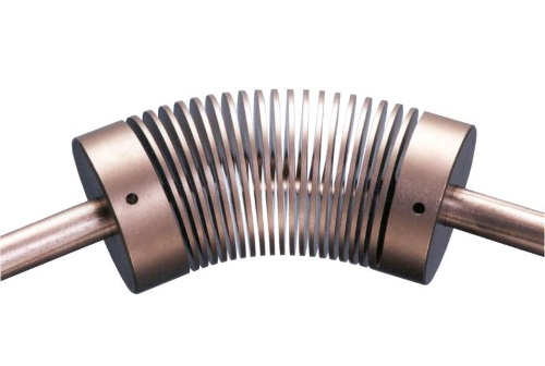
Bellows couplings are an assembly of two end pieces onto an electrodeposited nickel metal bellows. The bellows is fabricated using electrodeposition of nickel onto an aluminum mandrel. This is achieved by starting with an aluminum stock. We then machine the aluminum mandrel to have the internal dimension of the bellows. Then the aluminum mandrel is plated with electrodeposited nickel called FlexNickel. Once plated, the nickel is cut to define the ends of the bellows and expose the aluminum under the nickel.
Finally, the aluminum is removed chemically, leaving behind the nickel metal bellows. The finished nickel metal bellows can also be plated with gold, silver or copper for enhanced corrosion resistance or electrical conductivity.
Standard bellows couplings are not stored as finished products ready to ship. However, the varied hub sizes and the bellows are stocked such that orders for most sizes can be assembled and shipped within one to two weeks of ordering, depending on the quantity required.
From stock, we have many couplings available with sizes ranging from a 1/4 to 2.4-in. in diameter and from 0.48 up to 2.4-in. long with bore sizes as small as 2 mm and all the way up to 1-in. in diameter.
The available maximum torque transmission from our stock couplings varies from 2-in. ounces up to 4,000 inch ounces. Please note the units here. We’re not talking inch pounds but inch ounces.
Standard bellows couplings are suitable for service where the application temperature will vary from anywhere from -58 up to 260º F and applications such as resolvers and small actuators and motors. The temperature limitation for standard bellows couplings are limited due to the fact that the assembly is done with epoxy to bond the end pieces onto the bellows. Bellows couplings excel where the applications demands zero backlash, low windup and high torsional stiffness. The 100,000,000 cycle life will apply provided that the coupling is not used beyond its rated limits of compression, vending and offset. Further to this, it is important to note that these properties are mutually exclusive.
Servometer can provide custom units with varied capabilities above and beyond the previous mentioned limits such as nearly any bore size can be accommodated, unique flanges or end pieces can be attached to the bellows. Unique combinations of compression bending and offset with given torque and windup requirements can be achieved. Higher torque than 4,000 inch ounces is certainly possible and an operating temperature as high as 300º F are possible and temperature less than -58º F are feasible with a custom bellows coupling.
Increased and decreased temperature ratings would be achieved by assembling with an 95/5 tin silver solder. Naturally, a guaranteed cycle life will not be feasible at significantly lower temps such as cryogenic without testing. However, we do have bellows couplings operating in millikelvin experiments in quite a few different places. They’re certainly feasible to use for low temperature applications.
Servometer bellows couplings are used in many varied applications spanning industries such as medical, semiconductor, aerospace and military, among others. In the medical field, our bellows couplings are used for manipulating microscope stages, x-ray view boxes and other equipment such as dosing pumps. In the semiconductor field, the bellows coupling are used for position indication of lead screws, pick and place machines and other varied chip manipulation equipment. In aerospace and military field, the bellows couplings are used for adjusting targeting mirrors and lenses. Their lightweight construction helps them find service with instrumentation knobs inside and outside of the cockpit of an aircraft.
Also, on one very special application, with the M1 Abrams Tank, a Servometer bellows coupling assists with the main tank gun barrel system that allows it to remained aimed on target regardless of the changing position of the tank when moving.
I’d like to share with you some of the pitfalls of proper bellows coupling selection. Many people will call and give us geometry and think that the geometry of the coupling is all that matters but this isn’t true. The overall size of a bellows coupling does not necessarily indicate that it is suitable for the application. Many might assume that if they provide general envelope dimensions, that the allowable torque and the amount of compression and other properties would just fall on the line and be appropriate for their application but this is not the case. Geometry may limit the selection of available coupling from our stock offering but it does not guarantee the proper function of the coupling in service. If it is known that we are replacing a Servometer stock coupling that had a suitable service life with another Servometer stock couplings, then geometry will certainly help to determine a replacement. However, Servometer can make two bellows that look exactly the same act very differently just by changing the wall thickness by a thousandths of an inch or so.
If it is possible that a custom unit was used, then it is important to order the same custom unit or quantify all of the properties needed to design a custom coupling for your applications.
Another poor assumption is that the torque requirements will match the bore size but 3/8-in. shaft can handle much more torque than most Servometer coupling yet we offer larger bore sizes to match motors or shaft sizes that are used for lower torque applications such as that of a resolver. The size of the bore on a bellows coupling does not indicate that it is capable of handling as much torque that a shaft of the mating size might deliver.
Another poor assumption is that the last bellows coupling broke so higher torque or a different design is required. Cycle life is not related to torque but it is related to one rotation is equal to two cycles. The amount of compression offset or bending that is used at any one time and not just during operation will affect the cycle life.
No excursions can be allowed when considering life cycles. No allowance is made for over-compression or offset during installation and maintenance and down time. During these times, it is important to emphasize that the bellows can and will flex much more than what it was rated for on paper for the application. However, the rating applies to a reduced flexure to allow for the long cycle life that is specified and/or desired.
Some other pitfalls are in the operational environment similar to what Randy was stating. It’s important to consider that temperature, vibration, corrosion, these can all cause unique problems for good bellows coupling application and they can certainly be overcome if appropriately specified.
Speed of operation is important. For example Servometer bellows coupling are not speed balanced. If high speed greater than 3,000 RPM is required, then a third-party might need to be contacted to balance the coupling as you will require. It is also useful to note that the hubs are not in alignment with each other. If special alignment is required, then a custom design will be needed to support your application.
A lot of people wrongly assume they don’t have enough time for a custom design. The time invested in detailing the necessary performance characteristics of your application will pay off many dividends if done in advance. There’s a situation of paying down the time required now or after repeated failures due to a lack of planning.
Next, I want to just go over some geometry considerations. The design envelope will restrict how much selection you can have from readily available stock bellows. The outside diameter is another potential problem but can potentially be solved with a custom unit if considered. The thicker wall bellows might handle higher torque requirements than a same size bellows with a smaller overall diameter. Other performance requirements such as compression, offset and bending may suffer accordingly with an increase in wall thickness.
Sometimes, the stock unit can be quickly modified to accommodate a thicker wall. However, there are limits to how much thicker any one design can become and a custom unit may be designed for a thicker wall.
One simple solution not to be overlooked is that the bellows couplings are hollow and the shaft can protrude into the bellows cavity providing that does not interfere with the bellows wall. That screw-style bellows coverings are shorter by nature than compared to an integral clamping hub style. Generally speaking, set screws are typically more than sufficient for most applications using a bellows coupling as the allowable torque is not particularly high. Sometimes, a larger diameter can allow for more flexibility in a shorter bellows. Naturally, there are limits but if necessary, a custom larger diameter unit may be designed to accommodate a limited length application.
Torque requirements are also another major concern, of course, when considering a bellows coupling. The torque of the motor, though, is not the maximum torque of the system. Gearboxes act like a torque multiplier. If a coupling is used on the output shaft of a gear box, then the torque of the motor multiplied by the speed ratio may be a good starting point for determining your torque requirement.
The starting torque of the motor may be three to five times that of the operational torque of the system. It is important to consider the moment of inertia of the system when determining the maximum torque requirement of the coupling. When bellows couplings are used in compression, only 75% of the torque ratings should be used, since there is a potential for that bellows to buckle.
Buckling of bellows is similar to that of an overloaded column, in that it occurs when it is unpredictable in movement and likely increased windup, hence a bellows experiencing buckling will not provide reliable movement. Pulleys must also be considered to calculate the proper maximum instantaneous torque required for a bellows coupling. This similar to that of a gear box, however, with a pulley system, the value of the torque may increase or decrease, depending on its placement in the system.
The flexible movement considerations are also of interest, particularly with a flexible bellows coupling. Compression offset and bending are mutually exclusive. The percentage of each movement used with respect to its maximum when added together must be less than 100% or the bellows cycle life will be less than the standard 100,000,000 cycles.
Again, it is important to note that the bellows is much more flexible than that rated on the drawing or catalog, since it can easily move more than the values listed on the drawing, any movement beyond these limits will reduce the cycle life of the bellows accordingly.
Additional flexible movement considerations. If an increase in compression offset or bending is required, the coupling may be de-rated.
The operational environment is of natural concern. 260º F is the maximum operating temperature of a standard bellows coupling. There is a maximum operating temperature of 350º for a Servometer bellows alone. The bellows limiting temperature is due to the fact that above this temperature, the bellows will start to anneal. If the material anneals, then it will lose its temper and not respond like a bellows or spring any longer.
The minimum operating temperature of the bellows is not necessarily a known hard value. There are customers using Servometer bellows in millikelvin temperature experiments with custom units. The bellows do operate acceptably in this environment, however the minimum operating temperature of a Servometer standard coupling is minus 58º F. This is due to a physical limitation of the epoxy used for assembly.
Corrosion resistance is also of concern. Servometer bellows coupling are an assembly of one bellows with 2 hubs that attach onto the shafts. The bellows is comprised of Servometer nickel and is similar to that of nickel 200 alloy. The hubs are fabricated from 303 stainless steel. Aluminum hubs are also a potential supply for applications that require an extremely lightweight option. Naturally, many other materials for the hubs can be made available with a custom unit.
Now, I want to give you some guidelines for determining what you need for a custom design. Custom couplings with diameters as large as 9-in. in diameter and as long as 18-in. are possible for Servometer. In order to develop a custom design, we will need input on the following items to be best determine how to proceed. The temperature of operation for these couplings could be as high as 300º F and as low as minus 423º F for a custom design. Again, we know of customers using these bellows in millikelvin research. There isn’t a necessarily hard known value for lower temperature limit.
Corrosion protection of the bellows coupling may be enhanced with gold, silver or even copper plating if required for different environments in applications such as to maintain electrical conductivity. The type of movement required is one of the most important aspects to consider to create a design that will meet the cycling demand of the application.
The maximum torque must be determined based on how the coupling will be connected in the system and whether the system contains any gearboxes, motors and pulleys. Speed of rotation is important mainly for high speed applications, a special consideration may be required for balancing the coupling in the system.
In summary, we discussed the standard of custom. It really does depend on your requirements. If the application is straightforward and you only need bending or offset, then perhaps a standard unit may fit the bill. However, if many of the properties available are used or you require custom end pieces or specific spring rate, then a custom unit is most likely going to be required.
Know your geometry. Space limitations may determine for you what might be readily available from the standard bellows couplings but if you require a custom coupling, we mostly likely can overcome just about any space limitations you have. Larger diameters help carry higher torque allowances. Remember, the bellows coupling is hollow inside. If tight spaces demand that the shaft protrudes into the bells, it certainly can accommodate that.
Torque requirements. Naturally knowing how much torque is required is important but flexibility may also be just as demanding. Keep in mind the various torque multipliers that come into play for your project. Flexibility requirements, mutual exclusivity must be understood to prevent the potential of early failure for the bellows coupling. If all of one property is being used at one time, then you don’t have the other properties available anymore. Even the smallest amount of those other properties could exceed the rating of the bells and naturally, a lower cycle life should be expected.
Of course, it’s always nice to have a little bit more compression offset in bending available to allow for unaccounted or unintended movements such as when these parts are being placed into installation.
Operational environment, maximum temperature of 260º F and a minimum temperature of -58º F for standard bellows which are epoxied. Consider materials of construction. Bellows material is nickel and the end pieces are 303 stainless steel. If in doubt, ask about your specific environmental requirements.
Custom bellows coupling can overcome many challenges that would disqualify using a standard bellows. If the necessary details are understood and specified early, it’s likely that a good solution can be developed. Thank you for your time.
Questions:
Santora: Thanks, Rob. We’re going to open it up now for questions. We’re going to get to as many as we can but of course just remember that whatever we don’t get to during the webinar, you’ll be able to email Randy and Robert. First question:What’s a good first step for coupling selection?
Kingsbury: Probably the easiest way I think of for somebody starting is most of the coupling manufacturers currently have a coupling selector on their website. I’ve given you a screenshot of one that we have. I would say that’s probably a good spot. If you have some really extreme conditions, I would just call them. I think all the key players have applications. Engineering’s waiting to answer questions.
Santora: This next question is for you again Randy. What is the best type of coupling for a rapid movement pick and place type machine?
Kingsbury: Again, it comes down to the torque and torsional flexibility. It depends on many factors as I was mentioning. We have what are called multi-start couplings that give high torsional stiffness. In extreme cases, we’ve sent engineers to Servometer because the bellows coupling has a tremendous amount of torsional stiffness which is part of what effects your positioning accuracy on a fast-moving system. When you’re looking at a fast moving application, you want a product that has no backlash. When you get into coupling that are multiple pieces, you have the potential of getting into a backlash system which can make the positioning a real problem to compensate for.
Santora: Now, just to shift gears a second: Would you recommend keyways for all shaft sizes?
Kingsbury: No. A lot of our couplings, I certainly know in the ones we do at Helical, it’s really for the most part, when you get that 5 5/8th diameter and above is when the coupling within the keyways become relatively common. Some people go down to half inch but if you get smaller, expensive to make and really, the clamp has more than enough torque capacity to transmit the load.
Santora: Okay. The next question here, let’s see. Will all couplings be constant velocity?
Kingsbury: Wow! Yes. I’ll throw in my 2 cents. Really, a lot of the couplings. I know Servometer will be essentially constant velocity when you’re running at a constant load. The types that won’t are a type of coupling called a Cardan-style u joint. It’s where, as the angle gets larger, the variation between the input speed and the output speed oscillate. Unless you put them together in pairs and phase them properly, you will not have constant velocity. Especially in motion control, that can be a real problem. I don’t know if Rob has some thoughts on that.
Collins: I think you hit the nail on the head. It’s similar to your previous comment in that if it’s composed of multiple pieces, then it’s much more likely to be similar to backlash to have the potential for stored energy in the system than to actually have the ends rotating at slightly different speeds but otherwise, everything we’ve discussed really are constant velocity.
Santora: Okay, gentlemen. I think we’re going to try to squeeze in one last question here. Then, we’ll start wrapping things up. Question coming in. For a coupling with clamp-style fasteners, does the fastening torque matter or will it affect the functioning of the coupling? What if each side is tightened unequally?
Kingsbury: I’ll start and then get Rob’s input on that. The tightening torque absolutely makes a difference on the fastener. When you have a clamp and there is friction between the clamp and the shaft from tightening that cap screw- that transmits torque. I think most of the coupling manufacturers will give a recommended tightening torque which is basically the rating of the cap screw, typically. You definitely want to use everything you can to make sure it’s on there firmly and transmits the torque without slippage.
Collins: Yes. I agree again, Randy. I can’t think of any reason why you would want the uneven tightening of either end. The whole idea is to transfer that rotational movement from one end to the other. If they’re not tightened evenly, they’re certainly leads to problems of slip. It’s also possible they wouldn’t be tightened evenly if there were 2 different shaft sizes. That goes back to the cap screw size that was used for the clamp, as you mentioned. Otherwise, in the ideal world where both sides of the coupling are the same size, then I would think they should be evenly tightened.
Santora: Thank you so much, gentlemen, both of you for all the insights today. And once again, thank you everyone for attending this webinar from Design World.
Helical
heli-cal.com
Servometer
www.servometer.com