


Edited by Mike Santora
*Below is an excerpt from part two of a Design World webinar presentation by John Smihal of TB Wood’s Inc. Here, Smihal covers some best practices for understanding axial misalignment in sleeve coupling installation.
…Another type of misalignment is axial misalignment. In many applications, you need a coupling that can that accommodate some kind of axial misalignment, basically to accomodate thermal growth. This is common in sleeve-bearing motors where the rotor wants to find its magnetic center. Certain types of couplings are better at accommodating this than others.

Now, I’d like to talk about how to do basic straight edge/caliper alignment. Typically as you get into petrochem plants, for example, they’re moving away from simple straight edge misalignment and getting into reverse dial-indicator and laser. However, when you’re dealing with a sleeve-type coupling in a lower horsepower application, a lot of times you don’t have room for those tools. A lot of times these are going to be used in water pumps that are used in commercial buildings, for HVAC, for example, where maintenance techs don’t necessarily have access to that equipment or the expertise to use that type of equipment. The nice thing about a sleeve-type coupling is that it’s relatively forgiving. Straight edge and caliper misalignment is effective. It works and it’s going to get you as close as you need to be to get long life out of that coupling and out of the connected equipment. The basic tools required: you need a straight edge, calipers, torque wrench and appropriate sockets for the setscrews.
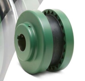
To install a sleeve-type coupling is quite simple. You have three components: two flanges and a sleeve. There’s no loose hardware. The installation is accomplished by basically installing the flanges on the shaft, positioning them properly and tightening the setscrews. When you install the sleeve, the sleeve must be seated fully in the flange and the sleeve should be centered in the shaft gap. You don’t want to leave a lot of axial play between the sleeve and the flange. You basically want to lightly seat it with hand pressure and make sure that you’re centering that sleeve in between the two shaft ends.
It is acceptable for the flanges to overhang the shaft ends by a little bit. For example, if you have a spacing that doesn’t closely align with one of the standard spacing configuration available in a manufacturer’s catalog, you can overhang those flanges off the shaft a little bit. The typical rule of thumb is that you need point-eight-five times shaft diameter engagement length.
It’s also very important to torque your setscrews to spec. Virtually every type of elastomer coupling is going to generate axial forces, and if you don’t have those setscrews tightened to spec, if you just give them a light twist with an Allen wrench, there’s a good possibility that the flange or hub can move on the shaft.
I’d like to come back to parallel alignment for a moment. With the sure-flex-style coupling, the sleeve couplings are manufactured to where the OD of the flange is held very tight relative to the bore. You have very tight run out tolerance and you can use the OD of the flange to do your alignment checks. With a straight edge method, you basically want to put the straight edge on the circumference of the flange and you want to check it in multiple places around the circumference. Do not rotate the coupling when you’re doing this.
After you’ve done your checks in multiple places, you essentially want to measure the gap between that straight edge and the opposing flange and compare that to your published misalignment limits. Every manufacturer’s going to publish some misalignment limits, and you want to make sure that you stay as close to zero as possible. Generally, we tell people to stay within a third of the published limits to allow for the coupling to do its job once the equipment is in operation.
For angular misalignment, you’re going to want to put your calipers on the back base of the flange near the OD and again check in multiple places around the circumference. Do not rotate the coupling. You want to measure any gap and compare that to the published limits in the manufacturer’s installation manual, and you want to correct that as required. Again, the closer you can get the alignment, the longer the coupling’s going to last, the longer the equipment’s going to last.
It’s also important to check alignment in the case of a pump, for example. Once the base plate is mounted and fully grouted, the pipes are connected. Typically a pump manufacturer’s going to do a misalignment on that pump package before it leaves the factory. It’s very important that once it gets out in the field and gets installed that alignment is checked because of all the things we talked about earlier. Base plates can move. You connect piping to the pump. It can move things around a little bit. You want to always check the alignment at the final installation.
It’s also very important to make sure that all hardware’s tightened, that the proper coupling guard is installed before operating the equipment, and you want to make sure you’re observing proper lock-out/tag-out procedures and wearing proper personal protective equipment before attempting installation and alignment.
TB Wood’s
www.tbwoods.com