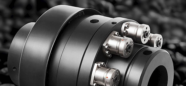
*Below is an excerpt from a Design World webinar presentation by Andy Lechner of R+W America. Here, Lechner covers some best practices for handling coupling installation in precision motion control applications.
Beyond that, and even on a newly assembled system, the real priorities in terms of performance, extended bearing life, increased efficiency and vibration reduction are very important. In larger power transmission drive lines, there’s also been a widespread effort to improve coupling alignment, as well as it being necessary in precision applications because of a lot of the couplings that are used there aren’t tolerant of large amounts of misalignment to begin with. In essence, all couplings should be aligned as well as practically possible, and in most cases, with few exceptions, they should be aligned as well as practically possible regardless of how much offset a coupling is designed or rated to be able to handle.Just a look at a typical coupling housing. Many suppliers of servo gear heads and linear modules and even some third-parties provide coupling housings that include alignment features.
In a typical servo drive line with a linear module you’re going to have a backlash free coupling tolerant of only a little bit of shaft misalignment. With too much shaft offset in a precision coupling, failure modes range from noise and generation of backlash over time as inserts wear, or complete failure, which is what will typically happen in the case of metal couplings, normally used for higher torsional stiffness and shorter settling times, more precision stroke. Obviously, you don’t want your coupling failing from misalignment, and in the world of precision motion control you’ll find alignment features all over the place. If you look at your servo motors or stepper motors or even gear head outputs, you’ll almost always see some sort of alignment feature that’s concentric to the shaft and bearings machined directly into the frame. Almost all precision linear motion systems also have them, and then there are generally accepted iso-fit tolerances that basically drive the dimensionally tolerances of male and female mating components to make sure that one manufacturer to another to another are going to fit up nice, end-to-end, concentrically.
When that’s done well, normally you’re talking about a maximum of a couple of thousandths, maybe, of parallel shaft misalignments, where pretty much all but rigid couplings can tolerate more than that with well-made housings.
R+W America
www.rw-america.com
Edited by Mike Santora
