


To save floor space, many machine builders are replacing an in-line process with a circular approach that tends to simplify the placement of rotational devices in a manufacturing environment. In assembly or multiple process applications, rotary index tables with multiple stations are gaining popularity. Index tables — fitted with numerous workstations where various sub-processes execute — rotate to the next station as each process is completed until the part is finished and removed. The types of processes occurring at each station are varied and may include machining, inspecting, cleaning, filling, or spinning a part.
The complexity of a rotary indexing process is apparent in the difficulties of incorporating a spinning axis station on a rotary indexing table. In precision applications, a servo or stepper motor is traditionally integrated into each station so the motor can spin the workpiece upon part arrival. This configuration requires that each station has an individual servo motor. This also necessitates the incorporation of the essential cable management requirements that feed power to the traveling motors, while also managing feedback information transmitted to the servo drives. Undoubtedly, this process includes a series of sliprings and the various correlated cable management elements.
For example, in an 8-station process where spinning occurs, each station requires a servo motor and the associated power and feedback elements, regardless of whether each individual axis station needs to spin. Therefore, if only three of the eight stations require a spin motion, the machine will need to carry five extra motors unnecessarily.
What if a solution was available that only engages the process stations needing to spin? Servo motors are typically coupled to their loads via a fixed member with many connection options, including rigid couplings, bellows style couplings, or couplings with flexible rubber inserts for misalignment.
Each of these connections will work wonderfully until the servo needs to be physically disconnected, as in the case discussed here. Limited options are currently available to fully disconnect the load from the motor. Items such as magnetic couplings (a design that always operates with a gap between two elements) struggle to maintain accuracy between the servo and the load due to the natural hysteresis in a magnet. Another option, engaging a V groove or drive cogs, does not address the need for exact alignment to prevent fretting corrosion on the cogs.
In considering each potential technology solution, maintaining a tight coupling with no slip is of paramount concern. In addition, alignment elements required for certain coupling types add more complexity to the application.
“The key to a successful solution is a coupling technology that is simple to align and will tolerate accelerating the station to the appropriate speed with no slippage,” Tony Kliber, IQa Engineering
In an actual machine example, an eight-station rotary table was required for processing a workpiece. Of those eight stations, three required spinning as part of the process. Each station required a different spinning profile, the most aggressive being an acceleration from 0 to 3000 RPM in .25 seconds. After the initial acceleration, the workpiece would decelerate to 0 in .5 seconds. At that point, it was critical that the workpieces were stopped in an orientation that prepared it for the next station (i.e., the servo could not slip at all during the accel/decel).

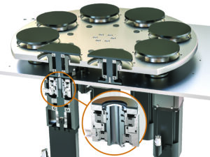
IQa Engineering established a solution that eliminates the extra servos and associated power and feedback complexities of conventional solutions for spinning requirements. The innovative approach uses a modified Nexen friction clutch design providing a simplified mount between the servo motor and clutch.
The clutch was mounted at three stations and is triggered at the appropriate station before spinning up. While this is not a typical use for the friction clutch, it held the most promise since its torque profile met the needs of this application. With the friction clutch engaged, the servo would then accelerate in 0.25 secs to 3000 rpm and hold speed throughout the specific process until stopped, at which point the clutch is disengaged.
As a precaution, the mechanism was fitted with a sensor to detect any slippage. Initial testing using the servo-driven friction clutch showed that no slippage occurred and that the solution provided the necessary spin function — while also simplifying the design, saving costs, and minimizing space requirements.
“We were excited to find that after extensive testing, no slippage was detected during acceleration, meaning our design concept was solid,” says Tony Kliber of IQa Engineering.
After successfully implementing the Nexen solution, IQa realized significant benefits to the system in comparison to having a servo at every station. The resulting system is lighter and requires less energy to operate, reduced cabinet space, smaller fuses, and less wiring — adding up to reduced manufacturing costs and improved OEE for the end customer.
Nexen
nexengroup.com