
For a coupling in a servo application to work properly, you need to satisfy a number of application factors including: torque, shaft misalignment, stiffness, speed, and space requirements.
Here’s a look at the available types of servo couplings and what you need to consider for each of them during the selection process.
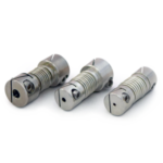
Beam couplings
Beam type couplings are manufactured from a single piece of material, usually aluminum, and use a system of spiral cuts to accommodate misalignment and transmit torque. For many applications, beam couplings are a good economical and maintenance free choice.
The single piece design transmits torque with zero backlash. Two basic variations exist: a single beam style and a multiple beam style.
The single beam style has one long continuous cut that usually consists of multiple complete rotations. It is very flexible and accommodates light bearing loads.

For many applications, flexible beam couplings are a good economical and maintenance free choice.

It is able to manage all types of misalignment, but works best with angular misalignment or axial motion. It is not well-suited to parallel misalignment because the single beam must bend in two different directions simultaneously, creating larger stresses in the coupling that could cause premature failure.
Under misalignment conditions, the long single beam allows the coupling to bend easily. But the relatively large amount of windup under torsional loads adversely affects the coupling’s accuracy.
Single beam couplings are an economical option best used in lower torque application and in connections to encoders and other light instruments.


Multiple beam couplings, which usually consist of two or three overlapping beams, attack the problem of low torsional rigidity. The use of multiple beams lets the beams be shorter without sacrificing much of the misalignment capabilities.
The shorter beams make the coupling torsionally stiff. Overlapping them so the beams work in parallel increases the allowable maximum torque making them suitable for use in light-duty applications with connections, such as from a servo to a leadscrew. A drawback is that bearing loads are increased by a sizeable amount over the single beam variety but, in most cases, remain low enough to protect bearings effectively.
Some manufacturers take the multiple beam concept to another level. Instead of using a single set of multiple cuts, they use two sets. The use of multiple sets of cuts gives the coupling additional flexibility to accept more misalignment, including parallel misalignment. With parallel misalignment, one set of beams bends in one direction and the second set bends in the other direction.
Most commonly, these couplings are made of aluminum, but they also come in stainless steel. Stainless protects against corrosion and increases coupling torque capacity and stiffness to sometimes double that of aluminum versions. The increase in torque and stiffness, though, is offset by a dramatic increase in mass and inertia. Keep in mind that in applications using smaller motors, a large percentage of the motor’s torque is used to overcome the inertia of the coupling.
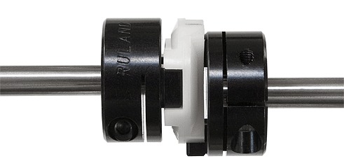
Oldham couplings
The Oldham coupling is a three-piece coupling comprised of two hubs and a center member. The center disk, which is usually made of a plastic or, less commonly, a metallic material, transmits torque. On the center disk, mating slots are located on opposite sides and oriented 90° apart. Drive tenons are located on the hubs. The slots of the disk fit on the hub tenons with a slight press fit that allows the coupling to operate with zero backlash. Over time, the sliding of the disk over the tenons will create wear to the point where the coupling will experience backlash. The disks are inexpensive items easily replaced, so a new insert will restore the coupling’s original capability.

The choice of materials for Oldham couplings depends on requirements for backlash, stiffness, vibration, and noise.
In operation, the center element slides on the hub tenon to accommodate misalignment.
The only resistance to misalignment is the frictional force between the hub and disk, Oldham couplings have bearing loads that do not increase as misalignment increases. Unlike other types of couplings, there are no bending members that cause bearing loads to increase as the shafts get out of alignment.
These couplings only allow a small amount of angular misalignment (less than one-half a degree) and axial motion (less than 0.005 in.), and are limited to speeds of 4000 rpm. Larger amounts of angular misalignment cause the coupling to lose its constant velocity characteristic, and axial motion is limited by the three-piece design of the coupling, which does not allow for use in push-pull types of applications. Because the center disk is a floating member, both shafts must be supported to keep the coupling from falling apart.

Bellows couplings easily bend under loads that result from angular, parallel, and axial motion.

Oldham couplings can handle relatively large amounts of parallel misalignment, from 0.025 in. to 0.100 in. or more depending on coupling size. Coupling manufacturers generally provide smaller misalignment ratings to obtain longer life ratings. These ratings can be surpassed at the expense of coupling life.
These couplings are available in a range of disk materials. The choice depends on requirements for zero backlash, high torsional stiffness and torque, or vibration absorption and low noise. Nonmetallic inserts are electrically isolating and can act as a mechanical fuse. When the plastic insert fails, it breaks cleanly and does not allow transmission of power, preventing other damage from occurring to machinery components.
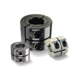
Zero backlash jaw couplings
Jaw couplings are either conventional straight jaw or curved jaw zero backlash versions. Conventional straight jaw couplings are not typically well suited to servo applications that require the accurate transmission of torque. Zero backlash jaw couplings, on the other hand, are well suited to servo applications. The curved jaws help to reduce deformation of the spider and limit the effects of centrifugal forces during high-speed operation.

Jaw couplings handle high-speed applications well, but are less able to handle large amounts of misalignment.

Zero backlash jaw couplings consist of two metallic hubs and an elastomer insert commonly referred to as a “spider.” The spider is a multiple-lobed insert that fits between the drive jaws on the coupling hubs with a jaw from each hub fitted alternately between the lobes of the spider. As in the Oldham coupling, there is a press fit between the jaws and the spider for the coupling to deliver zero backlash.
In contrast to the Oldham coupling, where the torque disk is in shear under torsional loads, the jaw coupling’s spider operates in compression. Be careful not to exceed the manufacturer’s rating for maximum torque, which can be significantly below the physical limitations of the spider. The spider can be compressed so that there is no longer a preload and backlash will occur.
Jaw couplings are well-balanced and able to handle high-speed applications, 40,000 rpm or more. They do not handle very large amounts of misalignment, especially axial motion. Large amounts of parallel and angular misalignment cause loads on bearing to be higher than those of most other types of servo couplings.
If a spider fails, the coupling will not disengage. The jaws from the two hubs will mate similarly to teeth on two gears and continue to transmit torque with metal-to-metal contact. Depending on the application, such action may be desirable or it could cause problems in the overall coupling system.
An advantage of the jaw coupling is the ability to mix and match spiders based on the application. Manufacturers of zero backlash jaw couplings offer multiple materials with different hardnesses and temperature capabilities that let you choose exactly the insert that meets the application’s performance criteria.
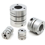
Disk couplings
At a minimum, disk couplings have two hubs and a thin metallic or composite disk that transmits the torque. The disk is fastened to the hubs usually with a tight fitting pin that eliminates any play or backlash between the parts.

Torsionally stiff, disc couplings can accept up to 5 degrees of misalignment with some of the lowest bearing loads available.

Some manufacturers offer disk couplings with two disks separated by a rigid center member attached to a hub at each end. The rigid center member is usually metallic, but plastic versions are available and can be used to electrically isolate the coupling. This configuration will reduce torque capacity and torsional stiffness.
The difference between the two variations is similar to the difference between the single beam style coupling and the multiple beam coupling with two sets of cuts. The single disk coupling is not adept at accommodating parallel misalignment due to the complex bending of the disk. The two-disk style allows each disk to bend in opposite directions to harness the parallel offset. The properties of this type of coupling are similar to those of bellows couplings. They transmit torque in a similar manner. The disks are very thin, allowing them to bend easily under misalignment loading, which allows the coupling to accept misalignment up to 5 degrees with some of the lowest bearing loads available in a servo coupling.
Torsionally, the disks are very stiff. The disk coupling has stiffness ratings slightly lower than that of bellows couplings. A downside to these couplings is that they are delicate and prone to damage if misused or installed improperly. For proper operation, take care to insure that the misalignment is within the coupling ratings.
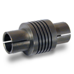
Bellows couplings
The Bellows coupling is an assembly of two hubs and a thin walled metallic bellows. In most cases, welding or an adhesive marry the hubs to the bellows.
Although other materials can be and are used, the two most common materials for the bellows are stainless steel and nickel. Nickel bellows are made using an electrodeposition method. It involves machining a solid mandrel in the shape of the finished bellows. The nickel is electrodeposited onto the mandrel, which is then chemically dissolved leaving behind the finished bellows. Manufacturers can precisely control the wall thickness of the bellows, creating thinner walls than is possible with other methods of bellows forming.

Rigid couplings can suit servo applications, especially if misalignment is tightly controlled.

The thinner walls give the coupling greater sensitively and responsiveness, which makes them suitable for precise small instrumentation applications. However, thinner walls also reduce the torque capacity of the bellows putting a limit on useful applications.
Stainless steel bellows are stronger than nickel versions and usually manufactured through hydroforming. A thin walled tube is placed into a machine and hydraulic pressure is used to form the convolutions of the bellows around specialized tooling.
The uniform thin walls of bellows allow it to bend easily under loads caused by the three basic types of misalignment between shafts: angular, parallel, and axial motion. Generally, bellows allow for up to 1 to 2 degrees of angular misalignment and 0.010 in. to 0.020 in. of parallel misalignment and axial motion.
The thin, uniform walls result in low bearing loads that remain constant at all points of rotation, without the damaging cyclical high and low loading points found in some other types of couplings. All of this is accomplished while remaining rigid under torsional loads.
Torsional rigidity is a key factor in the accuracy of the coupling. The stiffer the coupling, the more accurately it translates motion from the motor to the driven component. In the area of servo couplings, bellows type couplings are some of the stiffest available, making them ideal in applications that require a high degree of accuracy and repeatability. Some manufacturers offer bellows couplings with stainless steel hubs, which can be useful in applications requiring corrosion resistance, but their mass can be a factor in their operation. A coupling with aluminum hubs has very low inertia, a feature important for highly responsive systems. Some manufacturers balance their couplings to suit high-speed applications of more than 10,000 rpm.
Rigid couplings
These couplings were not often considered for servo application. Recently, however, smaller sized rigid couplings, especially in aluminum, operate in motion control applications because they offer high torque capacity, stiffness, and zero backlash. Torsionally rigid with virtually zero windup under torque loads, they are also rigid under loads caused by misalignment.
If misalignment is present in the system, however, the shafts, bearings or coupling will fail prematurely. Thus, the couplings cannot be run at extremely high speeds because they cannot compensate for thermal changes in the shafts from heat buildup in high-speed use. However, in servo applications where misalignment can be tightly controlled rigid couplings perform admirably.
Ruland Manufacturing Company, Inc.
www.ruland.com