


By Joyce Laird, Contributing Editor
What is torsional rigidity and why measure it?
Mike Parzych, Product Marketing Manager at GAM explains that Torsional rigidity is the ability of an object to resist torsion or in layman’s terms “twisting”, due to an applied torque. “While many factors may be involved, coupling torsional rigidity is very important to machine designs as small variations can significantly affect positioning accuracy or constrain cycling speeds,” he says.
How is torsional rigidity measured for couplings?
Parzych says that the best way to explain this is in the technical formula.”Torsional rigidity is a measurement of torque per angular displacement, and may be expressed as follows”:
Ct = Torsional Stiffness (Nm/rad)
Ct = M/ѱ
Where: M = Torque (Nm) and ѱ = Angular Displacement (rad)
By applying a known mass at a known moment arm, torque may be determined as follows:
m = mass (kg)
g = Gravitational Acceleration (9.81 m/s^2)
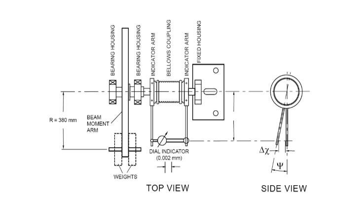
R = Moment Arm (m) = 0.38 m
M = Torque (Nm) = mgR
The angular displacement may be determined from the dial indicator reading as follows:
Δx = Indicator reading (mm)
τ = Indicator moment arm (mm)
tan (ѱ) = (Dx/ τ) (see Figure 1)
ѱ = arctan (Dx/ τ) (deg)
“Torsional stiffness is computed as follows”:
Ct = M/ѱ (Nm/deg)
Ct = M*180/π* ѱ (Nm/rad)
In the example test setup Parzych provides below, one end of a bellows coupling is attached to a fixed housing indicated in the drawing. The opposite end of the coupling is attached to a freely moving beam moment arm capable of being loaded with various weights. A dial indicator attached to the fixed and freely moving ends is used to measure the coupling’s torsional deflection under varying loads. The fixture measures the coupling’s overall stiffness, including the end hubs and the bellows.
How important is proper measuring for couplings?
Parzych says that in most cases, it isn’t practical or necessary to test every component in the design, so theoretical values must be used for calculating system stiffness.
“However, different coupling manufacturers’ published stiffness ratings can vary widely depending on the test methods used, and there can also actually be significant differences between published and measured values. For the engineer, that should serve as a caution when engineering a motion device whose performance relies heavily on overall stiffness. If there is an established set of evaluation protocols that faithfully model the performance characteristics, then you can be confident you’re getting the overall stiffness and system performance you intended,” he adds.
For expanded details on the subject matter, along with coupling stiffness test results conducted by an independent testing firm, please view the following link: http://goo.gl/NNPCBn
How do you select the right one for your application?
He notes that the right coupling selection will ultimately depend on the application requirements and machine throughput goals. If a designer is looking to improve machine positioning and cycle time, a focus on improving powertrain stiffness may be a high priority. In combination with other design changes, selecting a coupling with a higher torsional rigidity value can help to limit lost motion from torsional wind-up and improve overall system stiffness. Couplings with shorter overall lengths or specially reinforced bellows designs can be selected for higher torsional rigidity values. One thing to note is that while a shorter coupling will have a higher rigidity value (upwards of 60 to 70% in some cases), the misalignment compensation capabilities will decrease as well. “In consideration for this, GAM has several coupling series that have variable bellows length options (two bellows or four bellows), in which the designer can determine which is best for the particular application,” said Parzych .


Is there anything you need to watch out for when specifying?
Parzych says, “One thing we at GAM generally advise against is the use of a keyed hub connection for couplings. While keyed connections may help to ensure the coupling will not slip, they may also introduce lost motion into the system during cyclic applications as the keyway profile may wear over time. Reduced positioning accuracy due to lost motion (backlash) negates benefits gained from selecting a torsionally rigid coupling. If there is ever any question about how to handle a specific application, it is always best to ask an expert in the field.”
GAM
www.gamweb.com