Overload safety couplings also limit torque
July 1, 2011 by llangnau
Filed under Safety, Torque Limiters
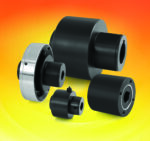
Zero-Max Torq-Tender Overload Safety couplings protect critical rotating power transmission components from torque overloads. Torq-Tenders serve both as a safety device and as a coupling in a power transmission system.
Torq-Tenders can be manufactured for systems requiring frequent washdowns such as food manufacturing and packaging applications. With the addition of an O-ring seal and simple housing modifications, Torq-Tenders resist contamination and are easily washed.
These couplings are simple to operate. When a power transmission system’s load exceeds the preset precision-tempered torque spring rating, the Torq-Tender’s drive mechanism pivots out of an engagement slot, disengaging the prime mover from the load providing overload protection. When the overload is removed and the speed is reduced, the Torq-Tender resets itself automatically. The single position re-engagement point maintains equipment timing and positioning.
Available in torque ranges from 2- to 3000 in.-lb, these couplings have tamper proof preset torque settings. The precision torque settings do not require costly and potentially risky calibration procedures.
As a coupling, the Torq-Tender can handle up to 1.5 degrees of angular misalignment and a maximum parallel misalignment of 0.005 to 0.015 in.
They are available in many standard sizes. From the smallest, TT1X (torque ranges 2 to 60 in.-lb) to the largest TT4X (torque ranges 750 to 3000 in.-lb), there are many precision preset factory torque ratings available.
Zero-Max
www.zero-max.com
Elastomer couplings with higher torque handling capacity
May 5, 2010 by llangnau
Filed under Elastomer, Flexible, Industry News, Torque Limiters
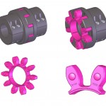
The growing popularity of curved jaw (elastomer) style couplings for precision applications has driven the need for couplings that handle more than the traditional torque capacity of 2,150 Nm up to a maximum torque of 25,000 Nm.
Available with split clamping collars or keyway and set screw connections, the three new body sizes allow for backlash free, vibration damping power transmission, paired with strong torque density. Dual flexture and jack shaft versions are also available for spanning longer distances and compensating for larger misalignments. Unlike the pre-existing range of R+W elastomer couplings, which use a single spider element between the new hubs, the new larger sizes will use individual vibration damping compensation elements to fit between each mating set of coupling teeth. These couplings are available in English and metric bore diameters up to 170 mm.
R+W America
www.rw-america.com
6 ways to assess torque needs for safety couplings
Safety couplings that operate on the ball detent principle primarily suit disengagement torque applications. But, with some modification, they can suit highly dynamic applications with resonant frequencies and torsional rigidity. Here is a brief examination of common equations used to calculate the following torques for safety coupling design in a drive system: disengagement torque, acceleration torque, acceleration and load moment, thrust force, resonant frequency, and torsional rigidity.
Disengagement torque. The disengagement torque must be greater than routine torque moments within a drive train. First, determine torque requirements within the drive train. In practice, a multiplication factor of 1.5 times the nominal operating torque is often adequate to accommodate acceleration moments and other influencing factors. To calculate minimum torque ratings for a drive train, use the following equation:
TKN ≥ 1.5 x TAS
Where:
TKN = torque in the drive train (Nm)
TAS = Peak torque in the drive train (Nm)
Peak torque is usually taken from the rating plate on the given drive mechanism.
You can use the number 9,550 as a constant value to convert power into Nm. Thus:
TKN ≥ 9,550 x PAN/n x 1.5
Where:
PAN = Power of the driving side (kW)
n = speed (rpm)
Acceleration torque. The acceleration torque method is a more accurate technique. In addition to angular acceleration, it makes allowances for peak torque on the driving side, the mass distribution, and the moments of inertia inherent to the driving and driven ends. With the help of a correction factor (surge or load factor) established according to the machine and application, acceleration torque can be determined using this method. Normally, a distinction is made between three types of surge or load factors:
SA = 1 (harmonic strain)
SA = 2 (periodic strain)
SA = 3-4 (non-periodic strain)
The following equation reflects these relationships:
TKN ≥ α x JL ≥ (JL/JA + JL) x TAS x SA
α = Angular acceleration (s-2)
JL = Moment of inertia on the load side (kgm2)
JA = Moment of inertia on the driving side (kgm2)
SA = Surge or load factor
Acceleration and load torque. The most accurate but complex assessment of torque for the evaluation of safety couplings is the acceleration and load torque method (start-up under load). This approach simulates an application in which constant acceleration and deceleration under load conditions takes place. Load torque is used as an additive factor to acceleration torque.
The following equation, with differentiation of individual variables, describes this relationship:
TKN ≥ a x JL + TAN ≥ [(JL/JA + JL) x (TAS – TAN) + TAN] x SA
TAN = Peak torque for the load side (Nm)
These three design methods are based on manufacturer data for the drive and the load components. In addition to torque moments, only moments of inertia and potentially incurred acceleration are included.
Thrust force. Another option for assessing application torque is the thrust force method. This method can be applied to spindle and lead screw drives as well as toothed belt drives, depending on the design of the drive system.
In addition to overall thrust force for the entire unit, thread pitch and efficiency play substantial roles in the proper design of spindle and lead screw drives. Here is the equation for the applied torque:
TAN = (s × Fv)/2000 × ∏ × η
s = thread pitch (mm)
Fv = thrust force (N)
η = efficiency
∏ = pi
If the drive and load are not linked by way of a spindle or lead screw, but by a toothed belt drive, use the following equation to calculate the incurred torque:
TAN = (d0 × Fv)/2000
d0 = pinion diameter of the toothed pulley (mm)
Resonant frequency. Each body and component in the drive train has its own natural frequency. The resonant frequency of the coupling and the entire drive system can be approximated with the following equations. A prerequisite for the calculations is the summation of mass moments of inertia of the individual components to determine the total mass moment of inertia. The torsional rigidity of the entire drive train also has a big influence on oscillation. The equation for calculating the coupling’s resonant frequency in Hz is:
ƒe = 1/2p x √CT x ((JA + JL)/(JA x JL))
The equation for calculating the natural oscillation in speed is:
ne = 30/p x √CT x ((JA + JL)/(JA x JL))
ƒe = resonant frequency of the system (Hz)
CT = Torsional rigidity of the coupling (Nm/rad)
ne = Natural oscillation term of the system (rpm)
Torsional rigidity. Whether a machine is designed to be rigid or damping depends on the respective application. The rigidity of all individual components, including the coupling, should always be taken into account. In theory, if a body twists by a defined angle if it is subjected to a certain load (torque). The degree of twist depends on the rigidity of the body (countering the torque). This relation is expressed:
φ= 180/p x TAS/CT
R+W America
New: R+W Series SK2 Safety Coupling
January 29, 2009 by R. Nelson Parrish
Filed under Industry News, Safety
Completely corrosion proof for outdoor and wash-down applications, the R+W SK2 can be a failsafe solution to overload problems.
Torque overload protection is often overlooked in machine design until something jams resulting in expensive damage and down time. The R+W Series SK2 safety coupling was developed specifically for this purpose. It uses a patented ball detent system that is absolutely backlash free and will disengage within 1 to 3 milliseconds when an overload is detected.
Four versions are available including a single position, multi-position, load holding, and free wheeling. These couplings are preset in the factory to a customer specified disengagement torque and can be adjusted in the field after installation.
These unique couplings are manufactured with a stainless steel bellows exhibiting very high torsional rigidity with zero backlash. The moment of inertia is also very low due to its low mass and low weight, making them ideal for servo driven systems.
The SK2 couplings are available for a torque range of 0.2 to 1800 Nm (1.8 to 15,930 in. lbs.). Both shaft hubs are custom bored for shaft sizes of 4 to 80 mm (0.25in to 3.125in.).
More details at http://www.rw-america.com/torque-limiters/index.html


