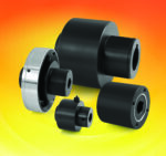
Torque Limiters that Keep Overload in Check for Heavy Equipment
July 7, 2010 by CouplingTips
Filed under Featured, Torque Limiters
A different approach is needed when designing mechanical torque limiters for high horsepower drives.
The basic principles of mechanical torque limiter design are similar to those that have been known since some of the first machines were built, yet it remains a dynamic field. Function, space restrictions, safety considerations and continuously changing machinery design drive the need for these components to evolve.

Typically, safety element torque limiters are supplied as a pre-set and self-contained package for integration into timing sprockets, sheaves and cardan shafts, like the one shown here.
In particular, high horsepower drives often call for mechanical design to be approached from different perspectives. As motors, gearboxes, and machines increase in size, power density can become disproportionate from one driveline component to the next, emphasizing the need for more rugged, robust and compact equipment. Precision mechanical components used in the packaging and light manufacturing automation industries, for example, may not be adequately scalable, and so be outsized quickly as drive requirements reach into the thousands of horsepower.
This disparity is seen in the design of modern torque overload release devices, the majority of which have torque release values inappropriately low for use on heavy equipment requiring operation and disconnect at torque levels beyond 10 KNm, such as large recycling equipment, gas turbines, windmill test stands, and industrial crushers. While market demand may be greater for smaller torque limiters, the availability of heavy-duty devices is critical as mass, inertia and destructive forces increase in high-powered machinery.
One exception to the rule of disproportionate size increase is perhaps the oldest and most rudimentary form of torque overload release device; the shear pin coupling. In this case, one or more pins link two rotating bodies with known yield strength located at a pre-defined radius from the center of the rotational axis. At some torque level near the calculated maximum, the pin(s) will break for a complete separation of the driving and driven shafts and fail to transmit the excessive torque.
Shear pins have protected rotating equipment for centuries, but they lack accuracy and can require much time to repair after overload. To maximize plant uptime and improve the accuracy of release torque, vendors have developed a variety of torque overload release devices with integral bearings and simple mechanical reset features. A limited number of these torque overload release devices have been reconfigured for high horsepower.
Spring tensioned torque limiters
The first widely used modern overload release devices came about in the 1930s for use in the steel industry where downtime can be expensive, and replacement of shear pins time consuming and dangerous. These parameters led to the development of the spring-tensioned form-fit torque limiter, which uses the same fundamental principle of a set release force located at a specific center distance.
In spring tensioned torque limiters, ball or roller bearings are precisely loaded into detents machined into an output flange that will break away quickly and accurately at a predefined torque level. This type of torque limiter will either ratchet or free wheel during and after overload, depending on size considerations and the rotational speed of the axis.

A slightly more sophisticated form of torque limiter is the ball-detent design. After overload release it reengages quickly.

The shear pin coupling is a rudimentary form of torque overload release device. It links two rotating bodies with known yield strength located at a pre-defined radius from the center of the rotational axis. It will break at a specific torque level and separate the driving and driven shafts so as not to transmit excessive torque. The problem with shear pins is that they lack accuracy and take time to repair.
In general, you can adjust the torque of these overload release devices by turning a single screw or spanner nut. Their ratcheting features represent a very fast and convenient means of recovery from overload, since all they require is either low speed operation or manual back driving of the axis after the blockage has been cleared. Since their initial development, hundreds of designs of “ball-detent” and “pawl-detent” mechanical torque limiters have been introduced, with a variety of adaptations made for high speed, high accuracy, light weight, and backlash free operation.
Higher horsepower needs
But, however convenient, these torque limiter designs tend to fall off at torque levels any greater than a few thousand Neutonmeters. The basic problem is that overload breakaway devices rely almost exclusively on torque as a measurable component of power.
Practical implementation of high horsepower drive systems normally involves a slow steady increase in the rotational speed of an axis, where the torque required for instantaneous acceleration would be overwhelming. Drive shafts and gearboxes, therefore, are not typically required to handle the severe peak torques associated with rapid acceleration and deceleration of the load inertia, as might be found in lighter manufacturing systems. As a result they tend not to be as large as a proportionate size increase might require in terms of pure torque capacity. This situation poses a torque density problem for mechanical overload devices.
Beyond 10 KNm common overload release designs become impractically large in outside diameter; the primary limiting factor being the spring set used to load the components together. Since industrial gearboxes, motors, and pumps tend to grow in diameter at a much slower rate than these types of torque limiters, as power increases there comes a certain point at which a traditional single spring form fit torque limiter makes no sense at all, and would tower over the equipment it was designed to protect. Clearly the lever arm component of the torque limiter design must be addressed. The simple answer is to substantially increase the force by which the individual transmission elements are loaded into the output.
There are two widely accepted approaches to overload release devices for torque in excess of 10 KNm, both of which seek to increase force over a reduced lever arm distance. One is a compact, simple design involving hydraulic pressure applied between the two otherwise free spinning surfaces. The other is based on a modified spring tensioned device similar to those previously addressed. Each has their advantages depending on the desired result.
Hydraulic versions
Hydraulic torque limiters basically apply hydraulic pressure between the two otherwise freely spinning surfaces. One or more chambers are inflated by hand to the desired pressure level, calculated as a function of release torque and based on charts provided in the manufacturer documentation. Special fluids guarantee a constant coefficient of friction throughout various operating conditions. These chambers let you apply a high level of force over a very small surface area. When the desired release torque is reached, the output will begin to slip against the input, causing the hydraulic valves to shear off, purging the fluid and fully releasing the input and output components of the torque limiter. Through an integral bearing, the load inertia coasts to a stop without further damage to the machine components or the torque limiter itself. Reconnection involves replacing the valves, refilling the chambers, and resetting the pressure.
Compared with shear pins, hydraulic torque limiters let you maintain strict control over the disengagement torque setting, which can be unpredictable with shear pins. They otherwise represent a compact choice for accurate torque overload release at tremendously high torque values, handling as much as 10,000 KNm. What they do not offer is a major reduction in the time required to recover from an overload event.
Modified spring tensioned device
For maximum plant uptime, a slightly more sophisticated form of the ball-detent design still offers the fastest means of re-engagement after overload release. Several decades ago, torque limiter manufacturers developed self-contained tangential force modules based on a plunger design. The torque density problems associated with traditional ball-detent torque limiters are then addressed through the use of one or more of these individually spring tensioned elements, which can tolerate very large tangential forces.

Spring tensioned torque limiters contain ball or roller bearings that are precisely loaded into detents machined into an output flange that will break away quickly and accurately at a predefined torque level. This type of torque limiter will either ratchet or free wheel during and after overload.
Since the individual torque transmission elements provide their own back stop for the spring tension, an array of small blocks are used, which are forced outward to clear the way for the plunger core to retract into the housing after sufficient tangential force actuates the system. The result is a “snap action,” which causes the plunger to quickly retract into the housing within a few milliseconds of overload. Once again, an integral bearing enables the load inertia to coast to a stop without further damage to the machine components or the torque limiter itself.
The key advantage to this design is the quick reloading of the individual elements into the output flange with either a gentle blow from a mallet or light pressure from a pry bar. Once the driving and driven components of the torque limiter are rotated back into the necessary orientation, re-engagement takes place quickly and easily. Depending on practical considerations, you can use pneumatic actuation systems to automate re-engagement, though future designs are likely to incorporate a more widely applicable, self contained and fully mechanical reset function.
As with traditional ball-detent torque limiters, spring tension is adjusted through the rotation of a nut, only in this case the elements are individually adjusted to the desired tangential force value, and a torque calculation is made based on the number of elements and their distance from the center of the rotational axis. While the earlier designs of safety element torque limiters involved special datasheets used in conjunction with measurements taken from the spring height, increasingly manufacturers indicate the correct nut location with a marked scale. You can make a coarse adjustment by adding or removing safety elements, which is made more plausible by torque limiter designs with the maximum number of receptacles pre-machined into the base element and with simple covers installed to guard them from contamination. The ability to make such adjustments means you do not need to ship the torque limiter back to the manufacturer for rebuilding in the case of gross miscalculation of the torque requirement.
Because of the modular design, safety element type torque limiters can be used for almost any torque release value, depending on the size and number of elements used, and limited by the maximum diameter allowed by adjacent equipment. For this reason, individual safety elements are normally made available for use into existing machinery designs or for custom coupling systems, including some used for linear force limitation.
For the most part, safety element torque limiters are supplied as a pre-set and self-contained package for integration into timing sprockets, sheaves and cardan shafts. Some manufacturers provide them as fully integrated flexible safety couplings, such as jaw, gear, and disc pack types to name a few. Custom options often include special materials, integral brake discs, high temperature felt seals, and added bearing support. As is the case in any field of design, manufacturers are driven to improve reliability and ease of use, while simultaneously reducing weight and space requirements for installation.
Compact Precision Torque Limiters from R+W America
March 30, 2010 by llangnau
Filed under Industry News, Torque Limiters
Based on a compact and simple design, the ESL series torque limiters from R+W offer accurate performance at a reasonable cost. Unlike traditional ball-detent torque limiters, the ESL spring loads two series of ball bearings against one another to create a rolling effect at overload.

The rolling effect reduces wear and at the same time lets the clutching interface serve as the bearing support during overload disengagements, saving space and cost. This torque limiter uses a specially developed “digressive spring characteristic,” so sensitivity to overload and torque disengagement accuracy are not compromised. Disengagement takes place within 3 milliseconds of overload, and at a value within +/-5% of the disengagement torque setting. The basic design mounts with a keyway and set screw; customized mounting attachments are also available. Technical specifications, solid models, and video are available at:
R+W America
http://www.rw-america.com/elastomer_couplings/torque-limiting-coupling-esL-t.php
Pneumatic Torque Limiter Provides Overload Protection
October 30, 2009 by CouplingTips
Filed under Torque Limiters
Nexen announced their TL Series pneumatically engaged, single-position torque limiters, delivering overload protection for industrial machinery. The TL Series uses a ball/detent interface and proximity sensor to immediately disengage the machine shaft when excessive torque or a machine jam occurs, effectively protecting downstream equipment and product from damage and decreasing downtime. Upon detecting the overload condition, the sensor instantly sends a signal to the torque limiter’s control valve, exhausting the air and disengaging the unit for a clean disconnect of power to the driven components.
By utilizing pneumatic actuation, TL Series units facilitate remote trip-out torque adjustment via an air regulator, allowing operators to optimize overload protection while the machine is in use-thus eliminating the need for inconvenient onsite adjustments. Each torque limiter’s interface has five ball/detents arranged in an asymmetrical pattern, assuring each engagement occurs in the same position and affirming machine components are accurately synchronized. The unique hard-chromed detent interface decreases drive-ring wear when the balls are pressed against the face during jog-to-position engagement, extending operational life as well as ensuring complete disengagement every time-without premature re-engagement.
Semi-open and totally enclosed, nickel-plated TL Series units are available. Semi-open units are sealed to keep contaminants out of the ball/detent area, while enclosed units are designed to protect the ball/detent and spline areas in washdown or other manufacturing environments where liquids are present. A variety of ball/detent sizes are available to provide a range of torque capacities, making the TL Series well suited for a broad application base, including packaging machinery, food processing, bottling, material handling and newspaper presses.

Several additional features of the TL Series ensure its long-lasting, dependable operation:
- The air chamber is sealed with o-rings to eliminate air leakage and minimize repairs, with backup rings to prevent o-ring dislocation, decreasing wear and extending the component’s operational life.
- Internal springs separate the ball and detent interfaces, preventing the ball from being forcefully removed from the detent-extending life and eliminating detent distortion, as well as preventing the torque limiter from re-engaging until the machine stops.
- The proximity sensor features an LED that illuminates to indicate when the torque limiter is engaged.
- Single-flex or double-flex couplings are available to deliver high shaft misalignment protection with zero backlash and excellent torsional rigidity.
http://www.nexengroup.com/nexen/index.jsp
Servo Torque Limiter from R+W America
June 16, 2009 by CouplingTips
Filed under Featured, Torque Limiters
Protection of an electromechanical system from torque overload is often assumed to be guaranteed by the current limits set in the drive parameters. But in the case of hard stops, impacts and other situations where overload occurs very rapidly, sufficient energy to do damage often exists in the rotating inertia driving the load.

R+W servo-rated torque limiters are accurate to +/-5% release torque and positively disengage the motor or gearbox shaft in 1-3 milliseconds. Patented pre-loads and a specially designed spring system remove backlash and guarantee a very low profile for higher release torques.
R+W America
www.rw-america.com/torque-limiters/index.html
Torque Limiters Tag-team to Prevent Overloads
December 16, 2008 by CouplingTips
Filed under Torque Limiters
For bottlers, protecting motion and assuring smooth, continuous operation in filler systems are critical in preventing system downtime. To guard against overloads and other system jam-ups, automated filling systems incorporate all types of devices including shear pins, electronic limit switches, and various types of mechanical stopping devices. These options may get the job done, but when they require repair, the systems must go down.

Elmar Worldwide Monoblock filler systems have speeds to 600 containers per min. The Company offers over 100 different models, from six to 72 stations, including rotary piston, bottom fill, gravity, and pocket modules. It uses Zero-Max torque limiters to protect from overloads.
For Elmar Industries, mechanical stops alone could not sufficiently halt the upward travel of the adjusting column with every cycle on one of its 100+ models – the Monoblock custom filler/capper
systems. At times, the upward force would overpower the mechanical stops, jarring them loose and sometimes knocking them off the system. The downward motion could develop too much force if the limit switch failed and the column bottomed out. This would jam-up the system. “What’s critical is to be able to control both upward and downward travel to avoid both of these problems even if the over-travel switches fail,” said Russell Wozniak, project engineer for Elmar.
Wozniak’s team turned to an alternative method for overload protection. Elmar now uses mechanical torque limiters because of their simplistic, fail-safe operation. On its Monoblock filler/capper systems, two different Zero-Max Torq Tender torque-limiting devices safeguard two separate machine functions. Both devices provide fail-safe jam-up protection.


The Zero-Max H-TLC torque limiter provides overload protection in the bottle height adjuster mechanism.
“We use the H-TLC-500 torque limiter in the motorized height adjustment mechanism, which raises and lowers the center column to adjust for different bottle heights,” reported Wozniak. This device prevents over-travel of filler heads. At the high and low point of travel of the filler head are mechanical stops. The motor-driven height adjuster assembly has a rotating shaft that connects to the elevation device at one end and the H-TLC torque limiter at the motor end. The H-TLC is located between the motor that powers it and the shaft leading into the height adjuster mechanism. It operates on a spring-loaded convex pin and detent design, which reacts to pre-determined overloads. When the load reaches the preset limit, a pin disengages from the detent, shutting down the system. Once the overload condition is corrected, the torque limiter can be reset fast and the system restarted. The H-TLC can quickly be adjusted for changes in torque as needed.
The Zero-Max face-mount Torq Tender is the second torque-limiting device in the system. It
connects to the primary drive train that moves the bottles through the system for filling, and protects the timing screw mechanism in the main gear drive from any kind of jam-up. Steel springs within the unit force metal slides against each side of a hardened cast steel pawl, holding it rigid with one end seated in a detent on the outer drive housing. During normal machine operation, the Torq Tender functions as a positive drive coupling. Input power transfers into the central assembly through this pawl. The outer drive housing and its driven shaft then rotate.


1. During normal machine operation, a hardened cast steel pawl is held rigidly between metal slides, with one end seated in a detent on the outer drive housing. 2. The pawl rotates out of its detent when excessive torque overpowers the springs.
When a load exceeds the rating determined by the precision tempered torque springs, excessive torque overpowers the springs, and the pawl rotates out of its detent. The central assembly is disconnected from the outer drive housing. This cuts power in the system, shutting it down.
Wozniak said that prior to the Torq Tender, a shear pin protected the feed screw drive. This was a problem because it required time to replace it following a jam-up. The Torq Tender, however, re-starts quickly, and it does not require tools. “You can manually re-set the torque springs of the Torq Tender with a simple full turn of the device. This puts the pawl back in its detent, and it re-engages the drive shaft. What’s more, Wozniak reported, “Once installed, you can forget about the Zero-Max torque limiters because they never need service. Ours have performed without problems for over five years with many installations operating twenty-four hours a day, seven days a week.”
Zero-Max
www.zero-max.com
Elmar Worldwide
www.elmarworldwide.com

