
2023 is off and running, but before we dive headlong into all the content we’re excited to bring you in the new year, we want to give 2022 a proper send-off. Here’s a recap of the 5 articles that most captured your attention on Coupling Tips this year. 5. JP Bouchard and Randy Disharoon at the […]
r+w america
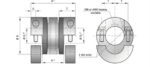
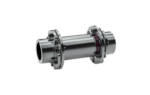
Metal bellows coupling with split hub from R+W
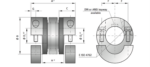
Design: * Both clamping hubs are completely separable, due to split hubs and two radial screws ISO 4762 on each hub. * Any imbalance of the clamping hubs is compensated for by balancing bores located on the inside of the hub. Temperature range: -30° C to +100° C (-22° F to +212° F) Backlash: Absolutely […]
Disc couplings for higher misalignment servo applications
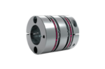
When precision machine drives are assembled without mounting pilots between the servo motor/gearbox and driven equipment, shaft misalignment becomes a key consideration in coupling selection. Most precision couplings are designed to compensate for a parallel shaft misalignment of between 0.1-0.2mm, which is perfect for piloted interfaces. When the connected components are mounted to different surfaces, […]
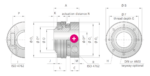
R+W MODEL BK8 flange-mounted precision bellows couplings
Increasing demands for high-quality motion transfer in compact and efficient machinery require that every component be evaluated, including connecting elements. When optimizing for highly dynamic motion, balance, and positioning accuracy, many mechanical designers are moving away from traditional shafted connections – opting instead for a more direct method of attachment for flexible joints. R+W has […]
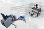
Strong… Stronger… R+W disc pack couplings
New configurations and solutions for extreme conditions. Robust and compact: R+W disc pack couplings are torsionally stiff, maintenance-free, and reliable even in some of the most difficult operating environments, including steel works, high-performance dynamometers, and industrial pump and process equipment. Fully metallic and made from high strength materials, they frequently operate in temperatures ranging from […]
SLN torque limiter with clamping hub for indirect drives
Design *with clamp collar and screw per ISO 4762 components of compact and rigid design with backlash-free interface *Temperature range: -30° C to +120°C (-22° F to +248° F) *Service life: These couplings are maintenance-free and stable over their entire service life if technical limits are not exceeded *Tolerance: Overall clearance between shaft and hub […]
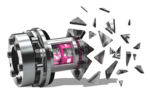
R+W: Coupling materials enable weight reduction up to 60%
The field of products in which an increase in speed and stiffness or energy savings can be achieved through a reduction in mass is very large. This area is not only limited to applications where lightweight construction has traditionally played an important role, such as in aerospace, but also includes production machinery such as industrial […]
R+W on the intelligent revolution in couplings for Industry 4.0

By Sascha Markert There are many cases where an expensive torque sensor would be excessive for measuring torque and speed. R+W Antriebselemente has launched a completely new alternative with its intelligent coupling. The product innovation presented here permits recording measurement data directly in the drive train, taking very accurate measurements and simultaneously user-friendly operation. Some […]
The R+W intelligent coupling
The “intelligent coupling” features direct recording of mechanical data in the drive train, taking accurate measurements through user-friendly operation. Some of the ideas underlying the Industrial Internet of Things (IIoT) include the optimisation of operational efficiency and cost reduction in production and monitoring equipment and machinery. All kinds of production processes can be better adjusted […]
Finalists announced for Mechanical category in LEAP Awards
Five finalists have been announced for the inaugural Leadership in Engineering Achievement Program (LEAP) Awards’ Mechanical Category. These finalists have created and incredible mix of mechanical component technology advances. The daunting task of judging this highly competitive category went to a panel of independent technical/engineering-oriented judges. Responsible for the Mechanical category were these four judges: Russ […]