6 ways to assess torque needs for safety couplings
Safety couplings that operate on the ball detent principle primarily suit disengagement torque applications. But, with some modification, they can suit highly dynamic applications with resonant frequencies and torsional rigidity. Here is a brief examination of common equations used to calculate the following torques for safety coupling design in a drive system: disengagement torque, acceleration torque, acceleration and load moment, thrust force, resonant frequency, and torsional rigidity.
Disengagement torque. The disengagement torque must be greater than routine torque moments within a drive train. First, determine torque requirements within the drive train. In practice, a multiplication factor of 1.5 times the nominal operating torque is often adequate to accommodate acceleration moments and other influencing factors. To calculate minimum torque ratings for a drive train, use the following equation:
TKN ≥ 1.5 x TAS
Where:
TKN = torque in the drive train (Nm)
TAS = Peak torque in the drive train (Nm)
Peak torque is usually taken from the rating plate on the given drive mechanism.
You can use the number 9,550 as a constant value to convert power into Nm. Thus:
TKN ≥ 9,550 x PAN/n x 1.5
Where:
PAN = Power of the driving side (kW)
n = speed (rpm)
Acceleration torque. The acceleration torque method is a more accurate technique. In addition to angular acceleration, it makes allowances for peak torque on the driving side, the mass distribution, and the moments of inertia inherent to the driving and driven ends. With the help of a correction factor (surge or load factor) established according to the machine and application, acceleration torque can be determined using this method. Normally, a distinction is made between three types of surge or load factors:
SA = 1 (harmonic strain)
SA = 2 (periodic strain)
SA = 3-4 (non-periodic strain)
The following equation reflects these relationships:
TKN ≥ α x JL ≥ (JL/JA + JL) x TAS x SA
α = Angular acceleration (s-2)
JL = Moment of inertia on the load side (kgm2)
JA = Moment of inertia on the driving side (kgm2)
SA = Surge or load factor
Acceleration and load torque. The most accurate but complex assessment of torque for the evaluation of safety couplings is the acceleration and load torque method (start-up under load). This approach simulates an application in which constant acceleration and deceleration under load conditions takes place. Load torque is used as an additive factor to acceleration torque.
The following equation, with differentiation of individual variables, describes this relationship:
TKN ≥ a x JL + TAN ≥ [(JL/JA + JL) x (TAS – TAN) + TAN] x SA
TAN = Peak torque for the load side (Nm)
These three design methods are based on manufacturer data for the drive and the load components. In addition to torque moments, only moments of inertia and potentially incurred acceleration are included.
Thrust force. Another option for assessing application torque is the thrust force method. This method can be applied to spindle and lead screw drives as well as toothed belt drives, depending on the design of the drive system.
In addition to overall thrust force for the entire unit, thread pitch and efficiency play substantial roles in the proper design of spindle and lead screw drives. Here is the equation for the applied torque:
TAN = (s × Fv)/2000 × ∏ × η
s = thread pitch (mm)
Fv = thrust force (N)
η = efficiency
∏ = pi
If the drive and load are not linked by way of a spindle or lead screw, but by a toothed belt drive, use the following equation to calculate the incurred torque:
TAN = (d0 × Fv)/2000
d0 = pinion diameter of the toothed pulley (mm)
Resonant frequency. Each body and component in the drive train has its own natural frequency. The resonant frequency of the coupling and the entire drive system can be approximated with the following equations. A prerequisite for the calculations is the summation of mass moments of inertia of the individual components to determine the total mass moment of inertia. The torsional rigidity of the entire drive train also has a big influence on oscillation. The equation for calculating the coupling’s resonant frequency in Hz is:
ƒe = 1/2p x √CT x ((JA + JL)/(JA x JL))
The equation for calculating the natural oscillation in speed is:
ne = 30/p x √CT x ((JA + JL)/(JA x JL))
ƒe = resonant frequency of the system (Hz)
CT = Torsional rigidity of the coupling (Nm/rad)
ne = Natural oscillation term of the system (rpm)
Torsional rigidity. Whether a machine is designed to be rigid or damping depends on the respective application. The rigidity of all individual components, including the coupling, should always be taken into account. In theory, if a body twists by a defined angle if it is subjected to a certain load (torque). The degree of twist depends on the rigidity of the body (countering the torque). This relation is expressed:
φ= 180/p x TAS/CT
R+W America
Six factors to remember about couplings in a motion system
Physical values such as torque, torsional rigidity, spring stiffness, moment of inertia, imbalance, and zero-backlash play a major role in coupling design. Here are a few facts to keep in mind when you design your motion system.
Torque (Nm): is the product of an acting force and the effective length of the acting force’s lever arm.
T = Fxr
T = Torque (Nm)
F = Force (N)
r = Lever arm (m)
With a force of 100 N and a 1 m long lever arm, you can generate a torque of 100 Nm. Or, you can generate a torque of 100 Nm with a force of 1000 N and a 0.1 m long lever arm. For couplings, a specific amount of torque can be achieved with a large outer diameter of the coupling and a correspondingly low acting force or with a small outer diameter and a correspondingly high acting force.
Torsional rigidity (Nm/rad): refers to the rigidity of a coupling when it is subjected to a torsional load. If the torque exceeds the maximum torsional value of the coupling, the coupling will no longer be strong enough to transmit the acting rotational force. Ex: If a coupling with a torsional rigidity of 10 000 Nm/rad is subjected to 10 Nm, the connection element will twist by 1/1000 rad. That is equal to an angle of twist of about 0.057 degrees (1 rad = 57°17’44.8”). For a torsionally rigid or vibration damping coupling, this angle of twist may still be within the admissible range. In practice, torsionally rigid couplings normally have a maximum angle of twist of less than 0.05 degrees and vibration damping couplings have a maximum angle of twist of less than 5 degrees.
Spring Stiffness (N/mm): is the counterforce exerted by the coupling in case of differentiated position of the axes in an axial, radial, and lateral direction. Ex: If the axial spring stiffness of a coupling is 30 N/mm, the coupling will exert a force of 30 N in the case of an axial displacement of 1 mm. These forces are important in a design with couplings, particularly when selecting bearings or other drive system components.
Moment of inertia: is the moment resistance when the rotational speed is changed. Normally, the lower the total weight and the smaller the outer diameter of the coupling body, the lower the moment of inertia. The reverse is also true, the higher the weight and larger the outer diameter, the higher the moment of inertia. This feature is important in highly dynamic applications because the drive has to generate sufficient torque to overcome a body’s moment of inertia to accelerate and decelerate.
Imbalance: in a drive system, imbalance should be as low as possible for smooth operation. Caused by asymmetries in the drive system where mass is distributed unevenly, it affects centrifugal forces on the entire drive system. It can be rectified by “balancing bores,” which are normally drilled directly into the location of the disproportionally high concentration of mass.
Zero backlash: is a lack of empty space or “play” when the rotational speed, direction of rotation, or torque changes. It does not mean that there is no angle of twist. Backlash is an important factor in predicting bearing life.
Information courtesy of R+W America
Silicone Insert Couplings from Sterling Instrument
November 9, 2009 by CouplingTips
Filed under Featured, Industry News, Rigid
New Hyde Park, NY — A new series of silicone insert couplings from Sterling Instrument (ISO 9001:2000+AS9100B Registered Manufacturer) features electrical isolation and no backlash. These metric couplings, identified as the S54HSAM… (clamp type) and S5PSAM… (set screw type) Series are stocked in 5 different bore sizes ranging from (6 mm to 16 mm).
![]()
These couplings have aluminum hubs with either set screws or clamps for fastening to shafts. The insert is silicone 40 ShA. Operating temperature ranges from -50°C to +150°C. They range in length from 26.5 mm to 57 mm. Their maximum speed is 5000 rpm.
They can be used in various applications and are especially able to accommodate tight or skewed connections. Quotes, online orders, available stock, and 3D CAD Model downloads are available at our new eStore at: www.sdp-si.com/eStore. SDP/SI offers over 1000 different types of couplings including inch and metric: magnetic, flexible, rigid, oldham, bellows, flexible shaft, spider type, Fairloc® shaft type, helical, slit-type, and neoprene flexible type couplings.
Sterling Instrument
www.sdp-si.com
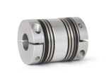
High Torque Servo Couplings
July 6, 2009 by CouplingTips
Filed under Servo
Heavy duty torque ratings and high strength conical clamping hubs make BK3 couplings the choice for high torque servo gearboxes. Manufactured with a double-walled stainless steel bellows to absorb parallel, angular and axial shaft misalignment, the BK3 has an extremely high torsional stiffness to complement its relatively very low moment of inertia – allowing it to handle rapidly indexing and reversing servo applications.

These unique couplings are manufactured with a tapered conical clamping element, which results in the highest shaft clamping forces, without keys, compared to any other hub design. The BK3 coupling also incorporates unique disassembly screws to aid the mechanic in tight spaces.
The clamping sleeves are custom bored on each side for shaft diameters from 10 to 80 mm ( 0.39 to 3.13 in.). Sizes are available for torque capacities ranging from 15 to 10,000 Nm (133 to 88,500 in. lbs.).
R+W America
www.rw-america.com
New Look for Huco Dynatork
February 11, 2009 by R. Nelson Parrish
Filed under Industry News

In February 2006 HUCO DYNATORK joined global Power Transmission group Altra Industrial Motion.
Altra Industrial Motion is a leading global supplier of quality power transmission and motion control products to most major industrial markets including, but not limited to food processing, packaging machinery, material handling, turf and garden and most others. Along with unparalleled delivery programs and superior customer service, the power transmission consumer, distributor and OEM who demand the best can count on Altra Industrial Motion.
Huco Dynatork is proud to be included in the presitgious list of Altra brands and we are delighted to unveil our new style, logo and color scheme with this exciting brand identity.
For more information about the Altra group visit www.altramotion.com


