

By Ringfeder editor Medium-duty applications — like starting and stopping medical diagnostic equipment and robotics — require reliable, precision-engineered brakes. Our AFS Multiple Disc Air/Hydraulic Spring Set Brake meets these requirements, delivering high-performance, fast and reliable action. Here’s how it works: The AFS applies braking torque when air or hydraulic pressure is removed from the […]
Safety
Zero-Max overload safety devices for corrosive and washdown applications
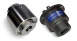
Zero-Max Overload Safety Devices protect motor and drive systems from overload while offering options to withstand corrosive environments and necessary washdowns. These options provide protection from direct water spray, washdown chemicals, detergents, chemical exposure, and debris. These unique Overload Safety Devices are ideal for applications ranging from food processing, packaging, commercial dishwashers, industrial parts washers, […]
Couplings for jaw or impact crushing plant applications
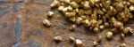
Without processing plants for crushed stone and gravel, many large construction sites cannot operate on schedule. Jaw or impact crusher plants are facilities that break rock into crushed stone or gravel. The crushing ratio depends on the subsequent processing requirements. The output for large plants is several thousand tons of rock per hour. Machine downtime […]
R+W heavy duty safety couplings for tunneling machines

Well developed road and rail networks are an essential requirement for a sound and efficient infrastructure in any country. Therefore, the tunneling machine field within the heavy machine construction industry will have plenty of contracts in the coming years. R+W ST safety couplings have been integrated in the latest generation of tunneling machines. On […]
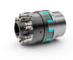
Heavy duty safety couplings from R+W
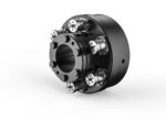
R+W has recently introduced two new smaller STN series safety couplings with conical clamping hubs, to bring heavy duty industrial style overload protection into midsize applications. The two new sizes, 2 and 5, cover disengagement torques ranging from 200 to 5,000 Nm, and shaft diameters from 45 to 80mm (1.750 to 3.125-in.). Taking advantage of […]
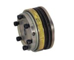
R+W safety couplings for wastewater applications

R+W has developed a standard model of corrosion proof ball detent safety coupling for clarifier drives in water treatment plants. The industry requires a well sealed, high-grade stainless steel mechanism to stand up to harsh conditions, resulting in the specific design criteria. The function of the ball detent torque limiter is to disengage the driveline […]
R+W releases the STB safety coupling with bellows coupling connection
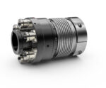
R+W brings heavy duty torque overload protection to dynamic precision applications with the new STB series safety coupling. Featuring a ball-detent safety element system, which disconnects drivelines within milliseconds of a torque overload event, this version offers precision transfer of motion and torque by using a symmetrically formed, torsionally rigid stainless steel bellows for the […]
Spindle safety system
Despite current CNC machine tool crash protection strategies which include both proactive avoidance through CAD/CAM programming and reactive damage reduction methods that include electronic sensors and mechanical overload clutches, machine tool crashes are still commonplace. In these machine tool crashes, tool collisions with high feed rates cause high forces on motor spindles. Depending on the […]
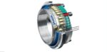
R+W Releases STE safety coupling with elastomer connection
R+W has recently narrowed the gap between its classic precision and industrial drive safety couplings with the new STE series. Featuring the well proven technology of the ball-detent safety element system, which disconnects drivelines within milliseconds of a torque overload event, this version is more cost effective and available in smaller sizes than the standard […]
How does a ball detent torque limiter work?
Coupling Tips.com asked KTR Engineering Services Manager, Chris Scholz about the basics of ball detent torque limiters. “In a ball detent design, there is some type of spring mechanism, or a spring disk, a curved spring disk, or a spring with a flat plate. A precision hole is also machined in that disk, or plate, […]