
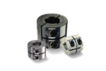
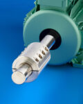
Ruland has expanded its range of short rigid couplings to include keyways and step bore sizes. This expansion gives designers a wider variety of standard short rigid coupling options for applications with space or weight restrictions or where designers prefer a simplified assembly with fewer screws than traditional rigid couplings. Many servo-driven applications in industries […]
Rigid
Rigid couplings for food equipment
Ruland rigid couplings have high torque capacity, accuracy, and repeatability, making them the ideal choice for food equipment. Designers of food processing, baking, and packaging equipment benefit from the Nypatch anti-vibration hardware, precision honed bores, and high torque of Ruland rigid couplings. Ruland straight bore rigid couplings are manufactured with precision honed bores for concentricity […]
Customizing torsionally rigid disc couplings with shrink disc for wind turbines

Couplings play a critical role in energy equipment — especially wind turbines. These durable components, which connect the gearbox to the generator, ensure the rotor blade system is operating as it should. Without the right coupling, a wind turbine can’t function properly, driving up maintenance costs and downtime. These scenarios are not welcome—especially since any […]
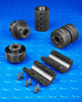
Rigid shaft couplings customized from standard templates
A new standard line of rigid shaft couplings offered with a choice of popular design templates to let users reduce the cost and delivery time of small quantity custom orders has been introduced by Stafford Manufacturing Corp. of Wilmington, Massachusetts. Stafford Customizable Shaft Couplings let users specify their own custom rigid couplings from 7 standard […]
The eight best ways to wreck your coupling driven system
Keeping a servo-driven system running at peak efficiency is no simple feat. Misunderstanding performance criteria such as misalignment, torque, or RPM can be all it takes to cause a critical failure. The following are the eight best ways to consistently sabotage or damage your coupling driven system (and how to avoid them in the future). […]
Rigid shaft couplings for attaching unsupported shafts
A full line of rigid shaft couplings that come in many styles to provide machinery builders with a wide variety of shaft attachment options are available from Stafford Manufacturing Corp. of Wilmington, Massachusetts. Stafford Rigid Shaft Couplings offer numerous design options for attaching unsupported shafts in a broad range of new and retrofit power transmission […]
Rigid shaft couplings perform special design functions
A full line of off-the-shelf specialty shaft couplings that are designed to meet different mounting and positioning challenges has been introduced by Stafford Manufacturing Corp. Stafford Specialty Shaft Couplings are each designed to perform specific functions. They include the 100:1 Phase Adjuster for precise static phase adjustment, PowerRing Rigid Shaft Couplings that transmit up to […]
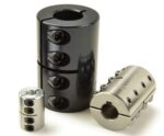
Dual-keyed rigid couplings prevent axial and radial slippage
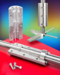
A line of rigid couplings that are suitable for heavy, suspended loads on shafts used in mixers, pumps, fans and related drive systems has been introduced by Stafford Manufacturing Corp. of Wilmington, Massachusetts. Stafford Dual-Keyed Rigid Couplings have axial and annular keyways to provide additional security for high torque and axial load applications. Designed to […]
Rigid couplings for mixers
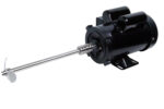
Mixers are one of the most common industrial applications. They feature a motor coupled to a paddle or propeller. While the connection is simple, mixers can be used in chemical, food, paint, adhesive and other industries complicating coupling selection. The versatility and flexibility of mixers are what makes them challenging to specify a coupling for. […]
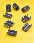
Rigid shaft coupling covers
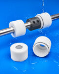
A new series of plastic covers for protecting rigid shaft couplings from hostile environments and permitting use in washdown applications is being introduced by Stafford Manufacturing Corp. of Wilmington, Massachusetts. Stafford Coupling Covers are designed to protect a rigid coupling from dirt, dust, and water and screw together tightly with an O-ring seal. Suitable for […]