Miniature Rigid Couplings Bore Size Down to 3mm
October 30, 2009 by CouplingTips
Filed under Jaw

Bores are precision honed in manufacturing process, assure tolerance of +.05/-.00 mm
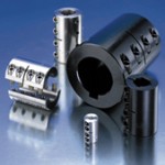
Ruland now offers miniature rigid couplings with bore sizes as small as 3 mm. Miniature rigid couplings are suitable for micro component applications where misalignment is neither present nor desired, including connecting line-shafts, attaching a motor to a gearbox, and servo applications. Offering high torque capacity, stiffness and zero backlash, Ruland’s rigid couplings are increasingly being used in precision motion control applications where misalignment is tightly controlled.
Ruland’s miniature rigid couplings are available in aluminum, carbon steel or stainless steel. The bores of the couplings are precision honed in the manufacturing process, assuring tolerances of +.05/-.00 mm. This enhances the overall performance of the couplings, especially important for applications that require strict control of shaft alignment and greater torque transmission ability. All rigid couplings from Ruland have Nypatch socket head cap screws for increased performance and reliability. This coating is designed to reduce screw vibration, which can cause the screws to loosen and torque transmission ability to diminish during the course of normal use.
Rigid couplings are available in one-piece clamp style, two-piece clamp style and set screw style versions, with or without keyways. A large number of standard sizes are available in straight and step bore combinations to fit shafts ranging from 1/8″ to 2″ in the inch dimension series and from 3mm to 50mm in the metric dimension series. Inch to metric conversion couplings are also available by special order.
Pneumatic Torque Limiter Provides Overload Protection
October 30, 2009 by CouplingTips
Filed under Torque Limiters
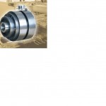
Nexen announced their TL Series pneumatically engaged, single-position torque limiters, delivering overload protection for industrial machinery. The TL Series uses a ball/detent interface and proximity sensor to immediately disengage the machine shaft when excessive torque or a machine jam occurs, effectively protecting downstream equipment and product from damage and decreasing downtime. Upon detecting the overload condition, the sensor instantly sends a signal to the torque limiter’s control valve, exhausting the air and disengaging the unit for a clean disconnect of power to the driven components.
By utilizing pneumatic actuation, TL Series units facilitate remote trip-out torque adjustment via an air regulator, allowing operators to optimize overload protection while the machine is in use-thus eliminating the need for inconvenient onsite adjustments. Each torque limiter’s interface has five ball/detents arranged in an asymmetrical pattern, assuring each engagement occurs in the same position and affirming machine components are accurately synchronized. The unique hard-chromed detent interface decreases drive-ring wear when the balls are pressed against the face during jog-to-position engagement, extending operational life as well as ensuring complete disengagement every time-without premature re-engagement.
Semi-open and totally enclosed, nickel-plated TL Series units are available. Semi-open units are sealed to keep contaminants out of the ball/detent area, while enclosed units are designed to protect the ball/detent and spline areas in washdown or other manufacturing environments where liquids are present. A variety of ball/detent sizes are available to provide a range of torque capacities, making the TL Series well suited for a broad application base, including packaging machinery, food processing, bottling, material handling and newspaper presses.

Several additional features of the TL Series ensure its long-lasting, dependable operation:
- The air chamber is sealed with o-rings to eliminate air leakage and minimize repairs, with backup rings to prevent o-ring dislocation, decreasing wear and extending the component’s operational life.
- Internal springs separate the ball and detent interfaces, preventing the ball from being forcefully removed from the detent-extending life and eliminating detent distortion, as well as preventing the torque limiter from re-engaging until the machine stops.
- The proximity sensor features an LED that illuminates to indicate when the torque limiter is engaged.
- Single-flex or double-flex couplings are available to deliver high shaft misalignment protection with zero backlash and excellent torsional rigidity.
http://www.nexengroup.com/nexen/index.jsp
Innovative Steel Bellows Coupling Released
October 26, 2009 by CouplingTips
Filed under Bellows, Featured
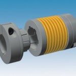
When first examined, steel bellows couplings seem to be the same superficially, but as one looks at the technical details, they will find there are substantial differences. The construction, structure and manufacturing quality of the steel bellows are the main factors for operational safety, reliability, service lifetime, misalignment capability and functional safety of the entire coupling. Other quality-influencing factors are the connection of the bellows to the hub components and the shaft-hub connections. They influence, for example, the transmittable torque and the coupling running characteristics decisively.

The backlash-free Primeflex steel bellows coupling
The backlash-free primeflex can be plugged in for easy installation and disassembly. It can be dismantled safely without putting the steel bellows at risk even after longer operating times. Herein lies one of the decisive technical advantages. On many other plug-in steel bellows couplings, there is a risk of damaging or even destroying the steel bellows when loosening the plug-in connection (tribo-corrosion effect on the conic hub). primeflex features specific material and geometry to fix this problem.
The extremely compact and high performance-density primeflex can be mounted easily onto the shafts via clamping or shrink disk connections. Another outstanding performance characteristic is the excellent misalignment capability of the new cost-effective steel bellows coupling. It compensates for axial, radial and angular shaft misalignments. The torque is transmitted via frictional locking or via frictional and positive locking. Furthermore, the internal mechanism integrates a stop in order to avoid bellows damages which can occur with excessive mounting pressure.
Primeflex Couplings currently come in three sizes that offer nominal torques ranging from 24 to 120 Nm. In the field of shaft couplings, Mayr power transmission has specialised in backlash-free couplings in servo power transmission services. With its steel bellows, elastomer and disk pack couplings, the company is able to provide the three most common constructional designs for this power transmission segment.
Steel bellows coupling are most often utilised to enable a power transmission between a motor and a reducer or a shaft, while allowing a correction of misalignment. The Main applications include all kind of machines (food processing, machine-tool, packaging…).
http://www.mayr.de/Startseite.1.0.html?&L=1
How to Properly Select a Bellows Coupling
October 6, 2009 by CouplingTips
Filed under Bellows, Featured
Properly selected bellows couplings result in the best control over the load in any servo application. Here are tips to ensure you choose the right size for the application.

Bellows couplings help maintain tight controls over loads.
For years, bellows couplings have been a mainstay for efficient motion systems because they offer high torsional stiffness, low moment of inertia, and minimal restoring forces under misalignment. They may help maintain tight control over loads, which is especially critical when considering that the flexible coupling often represents the point of least stiffness in an electromechanical system. In this way, couplings have a significant effect on the stability of the entire system, as well as the postional accuracy of the load. Bellows couplings benefits include misalignment compensation paired with precise transmission of velocity, angular positioning, and torque.
Most bellows couplings utilize a stainless steel tube which has been hydroformed to create deep corrugations that make them flexible across axial, angular, and parallel shaft misalignments while simultaneously maintaining the torsional rigidity inherent to a metallic tubular structure with a relatively large outside diameter. In shaft coupling applications, the stainless steel bellows absorb slight misalignments created by perpendicularity and concentricity tolerances between the mounting surfaces of the two connected components. They also absorb any axial force created by thermal expansion of the motor shaft during operation while minimizing torsional deflection and maintaining constant velocity. Exact transmission of velocity, angle, and torque, if not maintained, can compromise the operational performance of any servo motion system.
These scenarios place stress on the bellows, particularly parallel misalignment between the two shafts while transmitting torque. Lateral misalignment compensation causes the bellows to flex into an “S” shape with an angular bend at each end of the bellows that concentrates stress primarily on the end-corrugations closest to the mounting hubs. Excessive misalignment over time can harden these areas of the bellows making them brittle as they flex around circumferences. Enough torque can eventually cause the hub to tear away from the bellows during normal operation, an emergency stop, or aggressive acceleration.

Most bellows couplings use a stainless steel tube that has been hydroformed to create deep corrugations to make them flexible across axial, angular, and parallel shaft misalignments.
Torque considerations
While improved concentricity of the mounting faces of the coupled components (closer shaft alignment) can reduce lateral misalignment and ensure against failures, note that this mode of failure is closely related to the torque as well. High misalignment reduces the torque capacity of couplings. While a misaligned coupling will not normally tear until torque is applied, a precisely aligned coupling can transmit more torque than expected.
Because a range exists between misalignment and torque, bellows coupling ratings can vary. Hence, some manufacturers’ ratings are more conservative than others. For example, there are a variety of ratings for peak torque versus maximum misalignment values. Conservative coupling providers offer a shaft misalignment range in line with what the majority of electro-mechanical systems can handle, which is approximately 0.1 to 0.2 mm. Some are rated for slightly more or less misalignment. Peak torque ratings are generally similar across bellows couplings with this range of misalignment rating and a similar outside diameter. The associated torque ratings normally assume that the maximum misalignment condition will exist in the application.
This approach has been successful and normally allows for the coupling to fit well into assemblies involving the appropriately sized components. But not all coupling manufacturers use such a rating system. Some torque ratings may be inflated along with shaft misalignment tolerances. Check the documentation. Look for statements that say significant torque de-ratings must be applied in order to use a coupling’s flexibility. An improperly sized coupling can lead to significant pitfalls.

Some torque ratings may be inflated along with shaft misalignment tolerances. Check the product documentation.
Most bellows manufacturers agree on a combination of ratings that allow for a reasonable level of shaft misalignment to exist without yielding a maximum torque rating that would cause the coupling to be too large for an assembly. Some coupling manufacturers offer coupling designs with
additional corrugations and double flextures. These provide magnification of the lateral misalignment compensation within a given torque rating while maintaining a relatively high level of torsional stiffness.
Calculations to determine proper couplings
Proper bellows coupling selection should begin with a torque calculation. Quick factors to include in a bellows coupling selection are the peak torque capacity of the servo motor, multiplied by any application gear reduction ratio, and multiplied by a safety factor of 1.5. The appropriate bellows coupling should then have a torque rating greater than or equal to that of the calculated torque.

More precise calculations include the moments of inertia and actual torque required to accelerate the load by first overestimating the required torque of the application through the use of generalized service factors. Then, reduce the torque value by considering the moments of inertia of the drive and load. Inertia mismatch can be critical to coupling longevity as reflected load inertia in aggressive start/stop or reversing applications can produce significant spikes in torque. These spikes can exceed those estimated through the use of current limits into the drive amplifier.

Selection by torque is most common. However, calculating the required coupling torque rating can be skipped if their position accuracy requirements would result in a torsional stiffness value which would correspond to a torque rating in excess of the actual power requirements of the application.

A flexible coupling is typically the most compliant of components in any mechanical motion system making its torsional stiffness a critical factor in terms of maintaining positional control over the load. Since bellows couplings have the highest torsional stiffness of any servo motor coupling, they are employed in applications with high precision positioning requirements.
There are some rare cases in which the servo loop gains set high enough can result in a mechanical frequency which will excite the coupling’s natural frequency. In these instances, elevate the coupling torsional stiffness to avoid a situation where the rate at which the coupling springs back from a torsional impulse does not match when the next impulse would take place. Auto-tuning features in most modern servo drives have eliminated this potential problem for most applications. However, in some cases, this effort may be necessary. The following calculation allows for proper coupling selection based on mechanical resonant frequency.

Properly selected bellows couplings result in the best control over the load in any servo application. The selection criteria begin with ensuring that the coupling will have sufficient torque rating to accelerate the load, followed by checking that coupling misalignment tolerances are in line with practical expectations of the accuracy with which coupled shafts will be aligned.

Generally, higher misalignment tolerances can be achieved at potential compromise to torsional stiffness. However, in most applications, bellows couplings offer ample torsional stiffness. In cases where a coupling with a good mechanical fit has marginal torsional stiffness in light of stringent requirements, shaft alignment must be addressed in order to accommodate high stiffness requirements. A good rule of thumb would be to contact a coupling expert for servo coupling requirements to ensure optimal performance.
Discuss this on the Engineering Exchange:
R + W America
www.rw-america.com
Servo Torque Limiters
October 6, 2009 by CouplingTips
Filed under Featured, Industry News, Torque Limiters
Protection of an electromechanical system from torque overload is often assumed to be guaranteed by the current limits set in the drive parameters. But in the case of hard stops, impacts and other situations where overload occurs very rapidly, sufficient energy to do damage often exists in the rotating inertia driving the load.
R+W servo-rated torque limiters are accurate to +/-5% release torque and positively disengage the motor or gearbox shaft in 1-3 milliseconds. Patented pre-loads and a specially designed spring system remove backlash and guarantee a very low profile for higher release torques.

